Double-side staggered-tooth tau/2 low-thrust-ripple permanent magnet synchronous linear motor

A permanent magnet synchronous linear, low-thrust technology, applied in the direction of electrical components, electromechanical devices, propulsion systems, etc., can solve the problems of the average thrust of the motor, the increase of fluctuations, and the impact on the control accuracy of the linear motor system, so as to suppress thrust fluctuations, The effect of improving performance

Active Publication Date: 2018-10-16
NANJING UNIV OF AERONAUTICS & ASTRONAUTICS
View PDF5 Cites 3 Cited by
  • Summary
  • Abstract
  • Description
  • Claims
  • Application Information

AI Technical Summary

Problems solved by technology

But its disadvantage is that it reduces the average thrust of the motor, and at the same time changes the original characteristic that the secondary component bears the unilateral magnetic pull from the upper and lower primary components, which just completely cancels out, thus causing the secondary component to bear the unilateral magnetic pull and its fluctuations. Increase, which will affect the difficulty of motor assembly and affect the control accuracy of the linear motor system

Method used


Image

  • Double-side staggered-tooth tau/2 low-thrust-ripple permanent magnet synchronous linear motor
  • Double-side staggered-tooth tau/2 low-thrust-ripple permanent magnet synchronous linear motor
  • Double-side staggered-tooth tau/2 low-thrust-ripple permanent magnet synchronous linear motor

Examples


Embodiment approach 1

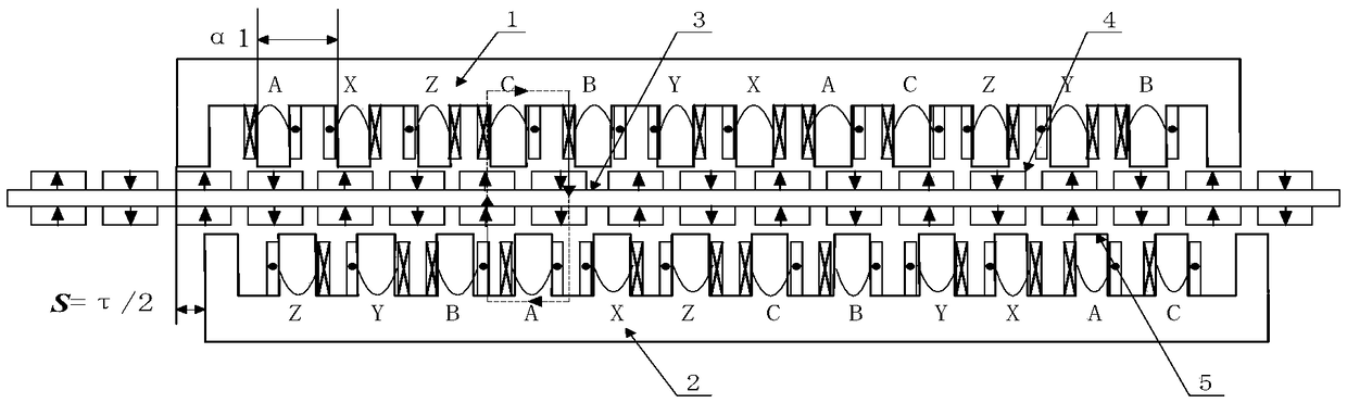
[0027] Such as Figure 1 to Figure 5 As shown, it is the first embodiment of the low-thrust fluctuation permanent magnet synchronous linear motor with bilateral staggered teeth τ / 2 of the present invention. The pole slots are matched with 14 poles and 12 slots. The motor includes a primary assembly 1 and a primary assembly 2 . and the secondary assembly 3, wherein the primary assembly 1 is composed of a core yoke 1-1, a core tooth 1-2 and an armature winding 1-3, and the core yoke 1-1 and the core tooth 1-2 form a slotted structure, and the electric The pivot winding 1-3 is wound on the tooth; the primary component 2 is composed of the core yoke 2-1, the core tooth 2-2 and the armature winding 2-3, and the core yoke 2-1 and the core tooth 2-2 form a slot structure , the armature winding 2-3 is wound on the teeth; the secondary assembly 3 is composed of a permanent magnet 3-1 and a yoke plate 3-2, each pair of poles includes four permanent magnets, and the permanent magnets loc...

Embodiment approach 2

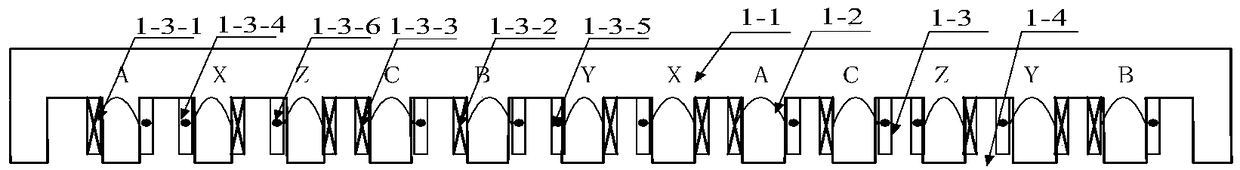
[0033] Such as Figure 6 , 7 Shown in , 8 is the second embodiment of the low-thrust fluctuation permanent magnet synchronous linear motor with bilateral staggered teeth τ / 2 of the present invention, and its pole slots are matched with 10 poles and 12 slots.

[0034] On the primary component 1, the A-phase winding 1-3-1 is set in the first slot and the third slot 1-4, the first slot is a half-filled slot, and the X-phase winding 1-3-4 is set in the In 2 slots; B-phase winding 1-3-2 is set in the 4th slot, Y-phase winding 1-3-5 is set in the 3rd and 5th slots; C-phase winding 1-3-3 Set in the 5th slot and the 7th slot, the Z-phase winding 1-3-6 is set in the 6th slot; the windings in the 1st-7th slot form a unit motor winding structure; the second unit motor The windings are arranged in the 7th to 13th slots, the phase sequence of the windings is exactly the same as that of the first unit motor, and the winding direction is completely opposite to that of the first unit motor....

Embodiment approach 3

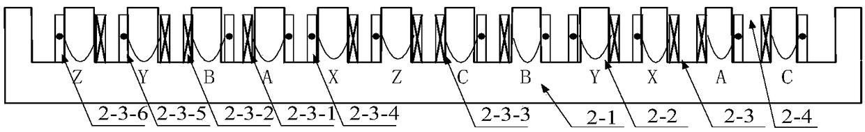
[0037] Such as Figure 9, 10 Shown in , 11 is the third embodiment of the low-thrust fluctuation permanent magnet synchronous linear motor with bilateral staggered teeth τ / 2 of the present invention, and its pole slots are matched with 20 poles and 18 slots.

[0038] On the primary component 1, the A-phase winding 1-3-1 is set in the first slot and the third slot 1-4, the first slot is a half-filled slot, and the X-phase winding 1-3-4 is set in the 2 slots and the 4th slot; C-phase winding 1-3-3 is set in the 4th and 6th slot, Z-phase winding 1-3-6 is set in the 5th and 7th slot Inside; B-phase winding 1-3-2 is set in the 7th and 9th slots, Y-phase winding 1-3-5 is set in the 8th and 10th slots; 1st-10th The winding in the slot forms a unit motor winding structure; the winding of the second unit motor is set in the 10th to 19th slot, the phase sequence of the winding is exactly the same as that of the first unit motor, and the winding direction of the winding is the same as ...


PUM


Abstract

The invention discloses a double-side staggered-tooth tau/2 low-thrust-ripple permanent magnet synchronous linear motor. A first primary assembly and a second primary assembly are both composed of anarmature winding and a primary iron core, each primary iron core is of a tooth groove structure, and the armature windings are wound on teeth; the first primary assembly and the second primary assembly are located on the two sides of a secondary assembly and form air gaps with the secondary assembly respectively; the secondary assembly comprises a yoke plate and a plurality of permanent magnets, each pair of poles comprises four permanent magnets, the first permanent magnet and the second permanent magnet of each pair of poles are located on the same side of the yoke plate, the third permanentmagnet and the fourth permanent magnet of each pair of poles are located on the same side of the yoke plate, the positions of the first permanent magnets and the third permanent magnets are opposite,the positions of the second permanent magnets and the fourth permanent magnets are opposite, the magnetizing directions of the first permanent magnets and the third permanent magnets are the same, the magnetizing directions of the second permanent magnets and the fourth permanent magnets are the same, and the magnetizing directions of the first permanent magnets and the second permanent magnets are opposite; the displacement of the first primary assembly and the second primary assembly in the transverse direction is S which is equal to tau/2, and tau is the polar distance of the motor. By means of the structure, the thrust ripple of the motor can be reduced, and meanwhile unilateral magnetic tension and fluctuation of the unilateral magnetic tension are reduced.

Description

technical field [0001] The invention belongs to the field of motors, in particular to a permanent magnet synchronous linear motor with bilateral staggered teeth τ / 2 and low thrust fluctuation. Background technique [0002] When the processing technology and precision of double primary permanent magnet synchronous linear motor are guaranteed, the normal electromagnetic attraction formed between the primary and secondary can basically cancel each other out on the middle part, so that the normal force generated in the motor can be Distributed to the bearings on both sides, there is a strong guarantee for eliminating the influence of the normal force on the performance of the motor. And the motor with bilateral structure can provide greater thrust in a given volume, which is more suitable for occasions with high thrust density. However, due to the common influence of end effect, cogging effect and armature reaction, this type of motor has the disadvantage of large thrust fluctu...

Claims


Application Information

Patent Timeline
Patent Type & Authority Applications(China)
IPC IPC(8): H02K41/03
CPCH02K41/031
Inventor 黄旭珍周文帅李静郝振洋周波
Owner NANJING UNIV OF AERONAUTICS & ASTRONAUTICS
Why Eureka
Try Eureka