
Multi-functional cupping device

A cupping and multi-functional technology, applied in the field of multi-functional cupping devices, can solve the problems of skin capillary rupture and congestion, increase the content of thrombosis-causing substances, and burn patients with easy burns, so as to increase tissue blood perfusion and prevent thrombotic diseases. , the effect of reducing the content of thrombogenic substances

Pending Publication Date: 2018-10-19
夏吉友
View PDF6 Cites 3 Cited by
  • Summary
  • Abstract
  • Description
  • Claims
  • Application Information

AI Technical Summary

Problems solved by technology

In addition, during the cupping process, the temperature inside the cup will gradually decrease with the continuous increase of negative pressure, and blood coagulation is prone to occur in a low temperature state, thereby increasing the content of thrombogenic substances in the blood, resulting in thrombotic diseases
At present, the current method of cupping to create negative pressure is generally to light alcohol sparks or other small amount of combustibles in the cupping tank, use physical methods to create negative pressure, and use heating, which has the following disadvantages: First, the flame falls during the ignition process For those who are prone to burns, at the same time, due to the large negative pressure in the cupping tank during the treatment process, it is easy to cause excessive rupture and congestion of capillaries on the skin and lose the therapeutic effect; the second is when the cupping tank is removed due to the negative pressure after the cupping session inflict pain on the healer

Method used


Image

  • Multi-functional cupping device

Examples


Embodiment Construction

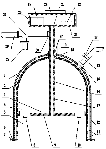
[0017] Such as figure 1 As shown, a kind of multifunctional cupping device of the present invention comprises cupping pot body 1, support plate 3, connecting pull rod 13, operating handle 21 and controller, and described cupping pot body 1 is made of outer casing and inner casing and has Opening double-layer hollow structure, and a closed chamber 2 is formed between the outer shell and the inner shell; the support plate 3 is arranged in the cupping pot body 1, and the cupping pot body 1 is divided into a first inner shell by the support plate 3 Chamber 4 and the second inner chamber 5 are provided with an air guide hole 18 communicating with the first inner chamber 4 at the top of the cupping body 1, and a sealing sleeve 19 is provided in the air guide hole 18, and the sealing The length of the cover 19 is set on the top of the cupping body 1, and the support plate 3 is connected with the operating handle 21 through the sealing sleeve 19 through the connecting rod 13; Air dev...


PUM


Abstract

The invention discloses a multi-functional cupping device. The device comprises a cupping jar body, a support board, a connecting pulling rod, an operation handle and a controller. The cupping jar body has a dual-layer hollow structure including an outer housing and an inner housing. The support body is arranged in the cupping jar body. The cupping jar body is divided into a first inner cavity anda second inner cavity through the support board. The top of the cupping jar body is equipped with an air guide hole communicating with the first inner cavity. A sealing sleeve is arranged in the airguide hole. The support board is connected with the operation handle through the connecting pulling rod by passing through the sealing sleeve. The device also comprises an air exhaust and discharge device and a medicine injection device, both of which communicate with the second inner cavity. The interior of the second inner cavity is also equipped with a pressure detector, a temperature detectorand a heating device, all of which are further electrically connected with the controller. The multi-functional cupping device can meet different treatment needs, is good in comfortability, excellentin effect, high in controllability, simple in operation and convenient in application and suitable for promotional use.

Description

technical field [0001] The invention relates to the technical field of medical equipment, in particular to a multifunctional cupping device. Background technique [0002] Cupping is a traditional Chinese medicine therapy in my country. It is a unique and effective treatment method summed up by the working people of our country in the struggle against diseases for thousands of years. Because of its convenient operation, remarkable curative effect and low cost of treatment, it is loved by doctors and patients. The healing mechanism of cupping therapy can be explained from two angles of traditional Chinese medicine and modern medicine. Traditional Chinese medicine believes that cupping can open the pores, strengthen the body and eliminate evil, dredge the meridians, and adjust qi and blood. Modern medicine believes that cupping can improve the function of phagocytes. After cupping, the activity of mononuclear phagocytes in the dermal connective tissue will be enhanced, blood ...

Claims


Application Information

Patent Timeline
Patent Type & Authority Applications(China)
IPC IPC(8): A61M1/08A61H9/00A61H39/06A61M37/00
CPCA61M1/08A61M37/00A61H9/0057A61H39/06A61H2201/5082A61H2201/5071A61H2201/105A61H2201/0207A61H2209/00A61M2205/05A61M2205/3368A61M2205/3341A61M2037/0007
Inventor 夏吉友潘燕罗天由
Owner 夏吉友
Learn More