Welding method for aluminum and copper heterogeneous metal materials

A technology of dissimilar metals and welding methods, applied in welding equipment, metal processing equipment, manufacturing tools, etc., to achieve the effect of improving uneven thermal deformation and large residual stress of joints, improving mechanical properties, and improving large residual stress of joints

Active Publication Date: 2018-10-19
JIANGSU UNIV OF TECH
View PDF7 Cites 1 Cited by
  • Summary
  • Abstract
  • Description
  • Claims
  • Application Information

AI Technical Summary

Problems solved by technology

[0005] Therefore, the technical problem to be solved by the present invention is to provide a brazing method for two heterogene...

Method used


Image

  • Welding method for aluminum and copper heterogeneous metal materials
  • Welding method for aluminum and copper heterogeneous metal materials
  • Welding method for aluminum and copper heterogeneous metal materials

Examples


Embodiment 1

[0028] The invention provides a welding method of 5mm thick 2024 aluminum alloy and red copper two dissimilar metal materials, comprising the following steps:

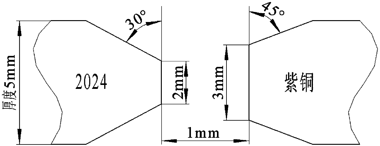
[0029] A. Use a file to make grooves on one side of two pieces of 2024 aluminum alloy and copper with a thickness of 5mm, remove oil and oxide film, and the final groove size is as follows: figure 1 As shown, the groove angle of the aluminum alloy is θ 1 =30°, after bevelling, the thickness direction dimension of the remaining butt joint in the middle is h 1 =2mm; the bevel angle of copper is θ 2 =45°, the thickness direction dimension of the remaining middle part after beveling is h 2 = 3mm.

[0030] B. Combine the aluminum alloy and the copper base material in pairs to form a butt joint, and number the first group and the second group respectively, and control the butt joint distance of d=1mm for both groups.

[0031] C. Perform pre-welding treatment on the copper base material in the first group, the voltage is ...

Embodiment 2

[0036] The invention provides a welding method of 8mm thick 2024 aluminum alloy and red copper two dissimilar metal materials, comprising the following steps:

[0037] A. Use a file to groove one side of two pieces of 2024 aluminum alloy and copper with a thickness of 8mm, remove oil and oxide film, and the final groove size is as follows: Figure 4 As shown, the groove angle of the aluminum alloy is θ 1 =45°, the thickness direction dimension of the remaining middle part after beveling is h 1 =3.5mm; the bevel angle of copper is θ 2 =60°, the thickness direction dimension of the remaining middle part after beveling is h 2 = 5mm.

[0038] B. Combine the aluminum alloy and the copper base material in pairs to form a butt joint, and number the third group and the fourth group respectively, and control the butt joint distance of d=1.5mm for both groups.

[0039] C. Perform pre-welding treatment on the copper base material in the third group, the voltage is 18V, the current is...


PUM

PropertyMeasurementUnit
Tensile strengthaaaaaaaaaa

Abstract

The invention relates to a welding method for aluminum and copper heterogeneous metal materials. The welding method for aluminum and copper heterogeneous metal materials mainly for problems that deformation of the 2024 aluminum alloy and the copper heterogeneous metal material in the T0 state of 5-8mm thick due to the difference in thermal conductivity and the unevenness of the joint structure. The main step comprises: (1) performing groove machining and welding assembling on the 2024 aluminum alloy and the copper base material respectively; (2) pre-welding the copper base metal, wherein the parameters are voltage 15-50V, current 60-150A, speed 1-10m/min; (3) brazing the 2024 aluminum alloy and the copper heterogeneous metal base material, wherein the brazing flux composition is AlCu2, thewelding parameters are voltage 20-60V, current 60-200A, speed 1-10m/min. According to the welding method for aluminum and copper heterogeneous metal materials, by selecting and controlling the groovesize, pre-welding and brazing parameters of different materials, the welding of two kinds of heterogeneous metals of the 2024 aluminum alloy and the copper can be realized, and the welding joint withexcellent welding performance is obtained.

Description

technical field [0001] The invention relates to a welding method for aluminum and copper heterogeneous metal materials, belonging to the field of welding technology. Background technique [0002] In recent years, with the emergence of new materials, the composite connection of dissimilar materials has been rapidly developed and applied, especially in aerospace, electronic machinery and defense industries. Due to the excellent mechanical properties of aluminum alloy and the good electrical and thermal conductivity of copper, aluminum-copper composite parts are more and more widely used. Therefore, the welding problem of Al-Cu dissimilar metal materials has always been the focus of research. [0003] The welding methods of copper and aluminum dissimilar metal materials mainly include fusion welding, solid state welding and brazing. For fusion welding, defects such as impurities and pores are easily produced in the weld, and because the melting points of aluminum and copper a...

Claims


Application Information

Patent Timeline
IPC IPC(8): B23K1/19B23K1/20
CPCB23K1/19B23K1/20
Inventor 谢利王江涛卢雅琳百志好杨林
Owner JIANGSU UNIV OF TECH
Why Eureka
Try Eureka