New energy electric vehicle

A technology of electric vehicles and new energy, applied in electric vehicles, electric power devices, circuits, etc., can solve the problems of increasing the economic burden of car owners and making it difficult to achieve dense coverage of charging stations

Active Publication Date: 2018-10-19
云南西塔新工业科技有限公司
View PDF9 Cites 6 Cited by
  • Summary
  • Abstract
  • Description
  • Claims
  • Application Information

AI Technical Summary

Problems solved by technology

[0004] The above solution provides a solution that uses robots to automatically replace batteries, but this requires corresponding automated charging stations, and it is difficult to achieve dense coverage of charging stations in a short period of time. If each vehicle is equipped with a set of automatic battery replacement equipment , and increased the economic burden on the owner

Method used


Image

  • New energy electric vehicle
  • New energy electric vehicle
  • New energy electric vehicle

Examples


Embodiment 1

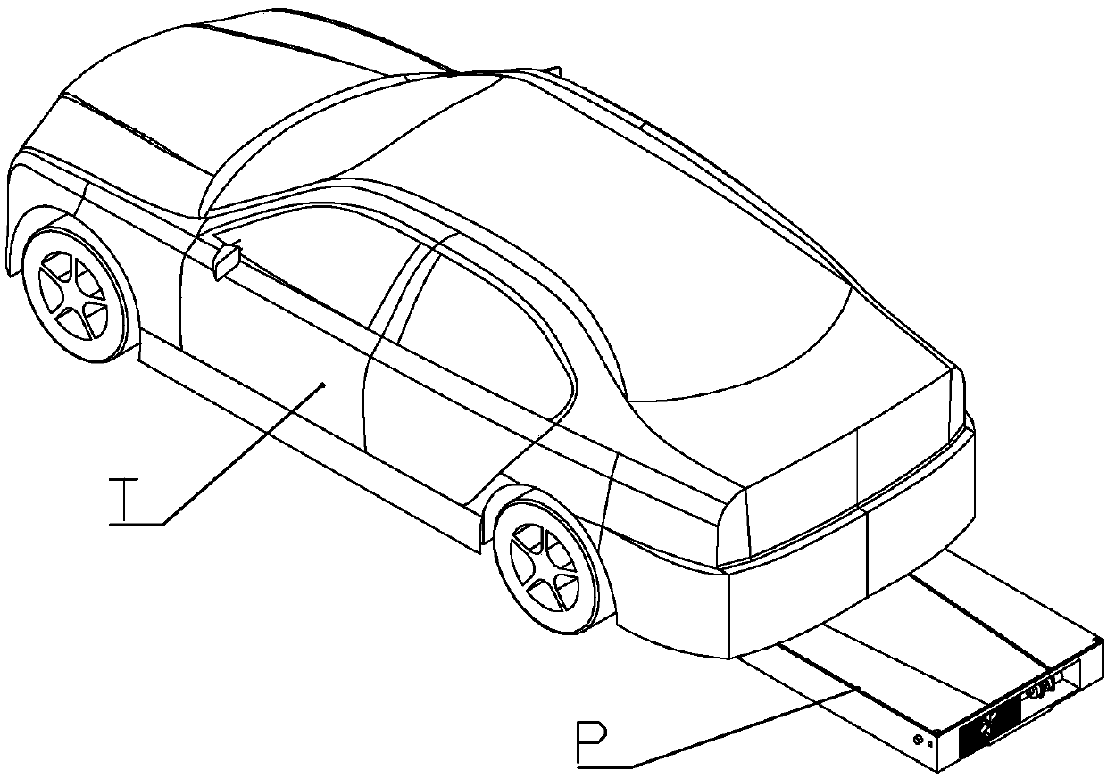
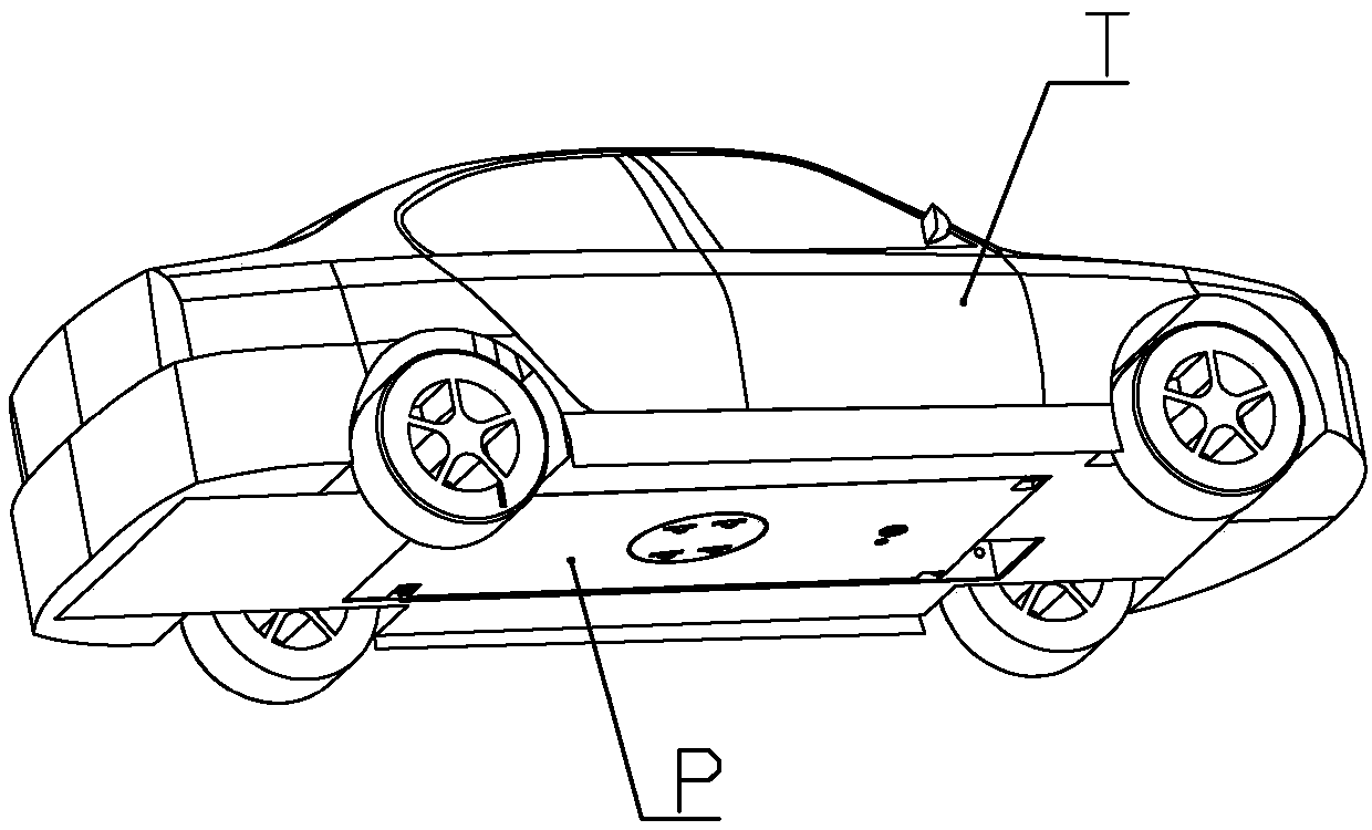
[0058] according to Figure 1 to Figure 10 As shown, this embodiment is a new energy electric vehicle, which includes a vehicle body T, and a battery unit P in the shape of a rectangular sheet as a whole is detachably mounted on the lower end of the vehicle body.

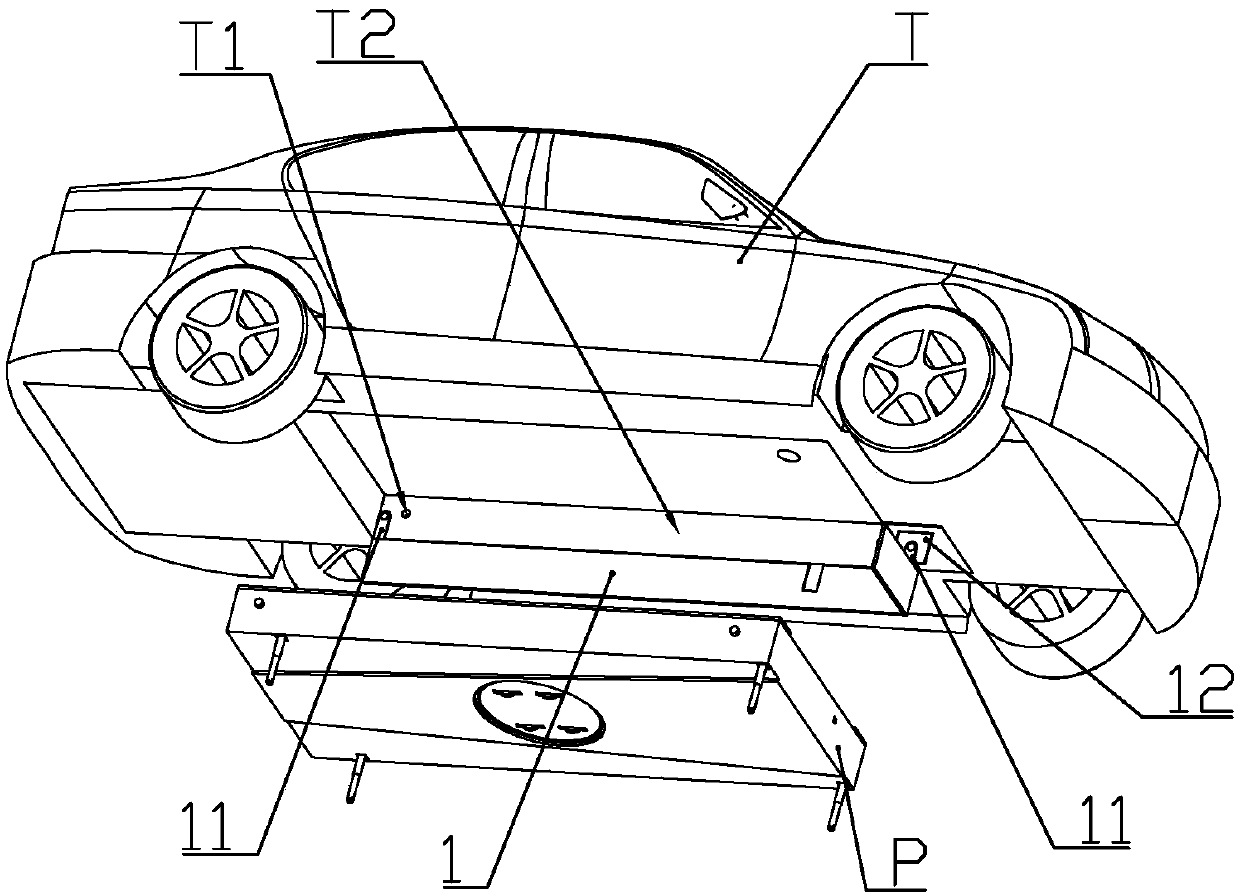
[0059] The lower end of the vehicle body is provided with a battery installation slot T2 for accommodating the battery unit, and a battery unit is installed on the left side along the length direction of the vehicle body in the battery installation slot for connecting the battery unit to the battery installation slot when the battery unit is installed in the battery installation slot. The positioning baffle 1 aligned with the battery installation slot.

[0060] The front end of the left side wall in the battery installation groove is equipped with a baffle motor 12 that drives the positioning baffle to extend or retract; the two ends of the positioning baffle along the length direction of the car body are rotatably ...

Embodiment 2

[0085] This embodiment makes the following improvements on the basis of Embodiment 1: an upper connection capacitor cavity 211 is formed on the cover plate of the housing at a position different from that of the mobile car, and an upper connection capacitor cavity 211 is slidably installed in the upper connection capacitor cavity. Seat 6, the upper end of the upper connection seat is equipped with 2-3 annular upper connection electrodes 61 arranged concentrically; the upper end of the upper connection seat is equipped with a permanent magnet 62; the lower part of the upper connection seat The outer wall is connected with more than two limit heads 63, and the side wall of the upper connection capacitor cavity is formed with a sliding limit groove 2112 that is slidably connected with each of the limit heads; the side wall of the upper connection capacitor cavity is also formed with wiring Port 2111, the upper connection electrode is electrically connected to the battery controlle...

Embodiment 3

[0093] combine Figure 11 to Figure 20 As shown, this embodiment makes the following improvements on the basis of Embodiment 1 or 2: the battery assembly is connected with a cooling assembly, and the cooling assembly includes a collector installed in the battery case for absorbing the heat emitted by the lithium battery. Heat pipes, radiators installed on the sides of the battery pack, and cooling pumps for driving cooling liquid to circulate between the heat collector pipes and the radiators.

[0094] The rear end of the battery case is formed with a radiator installation cavity 25, and the cooling pump and radiator are installed in the radiator installation cavity.

[0095] The radiator includes a heat dissipation plate 82, a heat dissipation seat 83 and a water wheel seat 84 which are sealed and connected in sequence; a heat dissipation channel 831 is opened on the end surface of the heat dissipation seat facing the heat dissipation plate, and the heat dissipation channel i...


PUM


Abstract

The invention belongs to the field of vehicles purely driven by electricity, and discloses a new energy electric vehicle. The new energy electric vehicle comprises a vehicle body, wherein a battery unit which is in a rectangular sheet shape is detachably mounted at the lower end of the vehicle body; a battery mounting groove for accommodating the battery unit is formed in the lower end of the vehicle body, and a positioning baffle for enabling the battery unit to be aligned to the battery mounting groove when the battery unit is mounted in the battery mounting groove is mounted in the batterymounting groove in the left side of the longitudinal direction of the vehicle body. According to the new energy electric vehicle, a mobile vehicle is arranged at the lower end of the battery unit, sothat the battery unit can move under remote control when being separated from the vehicle body; and in addition, by installing vertically arranged electric push rods on both sides of the battery unit,when the battery unit is installed on the vehicle body, the battery unit can be lifted into the battery mounting groove at the bottom of the vehicle body only by moving the battery unit directly below the battery mounting groove by the mobile vehicle and then controlling the extension of the electric push rods.

Description

technical field [0001] The invention belongs to the field of new energy vehicles, and in particular relates to an electric vehicle that obtains long battery life by quickly replacing batteries. Background technique [0002] The Chinese patent application with document number CN106295932A discloses a battery charging system for electric vehicles. More specifically, the batteries of commercially sold electric vehicles are leased. The battery leasing company also sets up a charging station. , only need to quickly replace the charged battery of the same type with the same type of battery that needs to be charged, which will greatly reduce the waiting time for charging. However, the above-mentioned scheme does not disclose the specific way of replacing the battery, because the storage battery used for electric vehicles is generally heavier, and it is too laborious to operate purely manually. [0003] The Chinese patent with document number CN201825013U discloses an automatic bat...

Claims


Application Information

Patent Timeline
IPC IPC(8): B60S5/06B60L11/18H01M2/10H01M10/613H01M10/625H01M10/6568H01M10/6554H01M50/249
CPCH01M10/613H01M10/625H01M10/6554H01M10/6568B60L58/26B60S5/06H01M50/20Y02T10/70Y02E60/10Y02T10/7072
Inventor 江桂英
Owner 云南西塔新工业科技有限公司
Why Eureka
Try Eureka