Structured-illumination optical section fluorescence microscopic imaging method and device thereof

A microscopic imaging and structuring technology, applied in the field of optical imaging, can solve problems such as unsatisfactory effects, and achieve the effects of convenient implementation, enlarged field of view, and improved resolution

Active Publication Date: 2018-10-19
ZHEJIANG UNIV
View PDF5 Cites 19 Cited by
  • Summary
  • Abstract
  • Description
  • Claims
  • Application Information

AI Technical Summary

Problems solved by technology

[0005] In order to improve the resolution of light-slicing fluorescence microscopy, researchers have made many attempts, combining super-resolution techniques such as stimulated emission depletion microscopy, structured light illumination, and single-molecule localization with light-slicing fluorescence microscopy. Combined with each other, trying to improve the resolving power of light sectioning fluorescence microscopy, but the results are not satisfactory

Method used


Image

  • Structured-illumination optical section fluorescence microscopic imaging method and device thereof
  • Structured-illumination optical section fluorescence microscopic imaging method and device thereof
  • Structured-illumination optical section fluorescence microscopic imaging method and device thereof

Examples


Embodiment Construction

[0044] In order to make the object, technical solution and advantages of the present invention clearer, the present invention will be further described below in conjunction with the embodiments and accompanying drawings.

[0045] Device embodiment

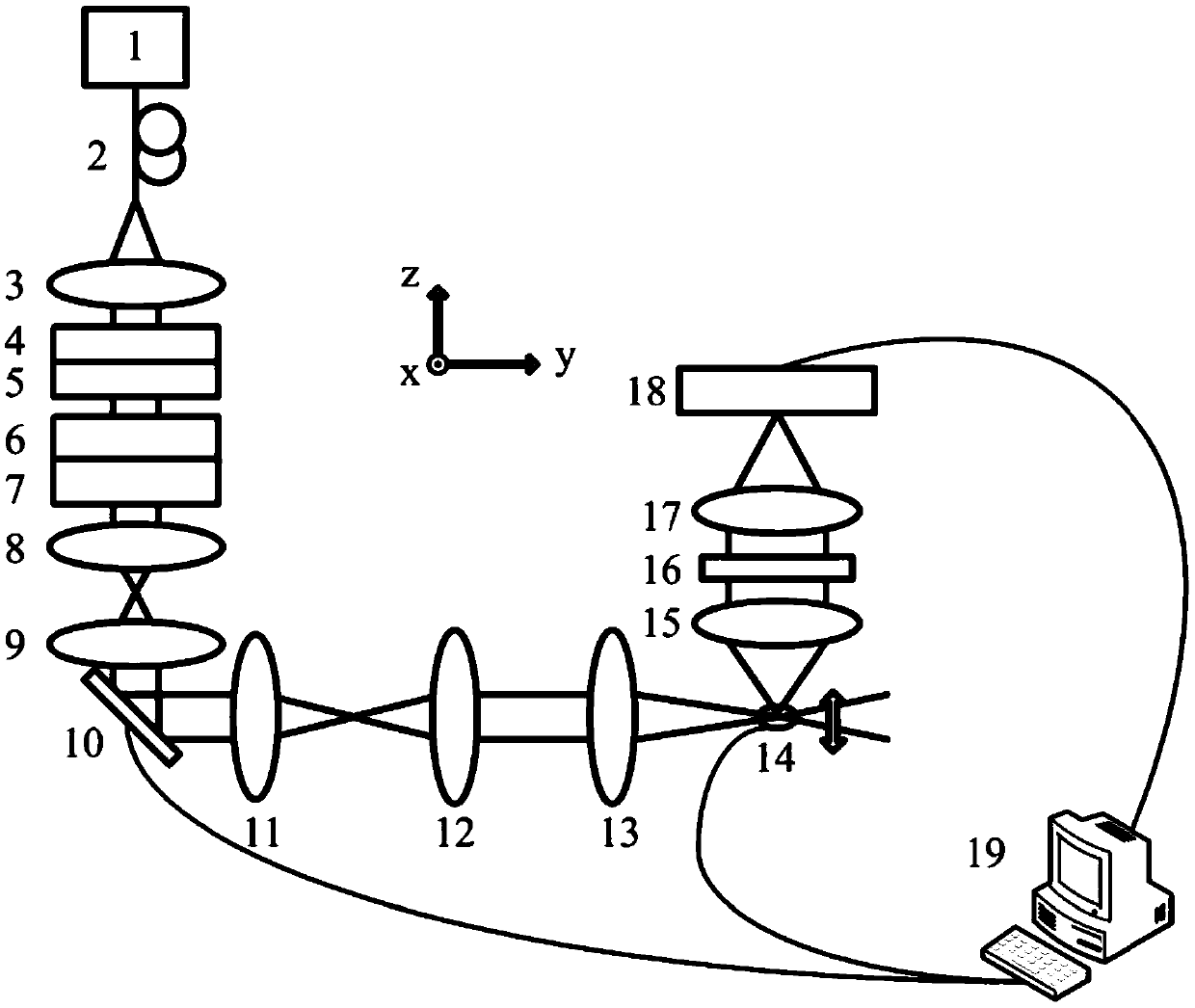
[0046] see figure 1 The optical section fluorescence microscopy imaging device of structured illumination in this embodiment includes a laser emission optical axis, an illumination optical axis, and a detection optical axis that can constitute a three-dimensional coordinate system. The mirror 10 is provided with a sample stage 14 at the intersection of the illumination optical axis and the detection optical axis. The X direction is the direction perpendicular to the illumination optical axis and the detection optical axis, the Y direction is the direction along the illumination optical axis, and the Z direction is the direction along the detection optical axis.

[0047] The laser output optical axis of this embodiment is provided...


PUM


Abstract

The invention discloses a structured-illumination optical section fluorescence microscopic imaging method and a device thereof, and belongs to the technical field of optical imaging. The device comprises: a light source; a sample stage for carrying a fluorescent sample; a detection system for detecting the fluorescence emitted by the fluorescent sample; a polarizer for changing a light beam into radically polarized lights and a radial polarization converter, which are sequentially arranged between the light source and the sample stage along a light path; a phase mask plate for carrying out phase modulation on the radially polarized lights; a diffraction grating for diffracting the modulated light beam; a galvanometer for moving an illumination pattern on the fluorescent sample, wherein thelight beam emitted by the galvanometer is irradiated onto the fluorescent sample from the Y direction, and the detection system collects the fluorescence from the Z direction; and a processor for controlling the galvanometer to move the illumination pattern from the X, controlling the sample stage to move in the Z direction, and processing and reconstructing a light intensity distribution image collected by the detection system in order to generate a three-dimensional image of the sample. The light beam formed by the device and the method has a small main lube and a large view field.

Description

technical field [0001] The invention relates to the technical field of optical imaging, in particular to a method and device for structured illumination optical section fluorescence microscopic imaging. Background technique [0002] The rapid development of biotechnology in recent years requires us to have a deeper understanding of physiological processes, which also puts forward higher requirements for 3D real-time imaging technology. However, the development of 3D real-time imaging technology also faces many challenges—successful 3D real-time imaging technology needs to simultaneously achieve high spatial resolution, high imaging speed, good optical sectioning ability, low photodamage and photobleaching ability. These characteristics are often contradictory. For example, if you want to obtain an image with a higher spatial resolution, it may take more time, which sacrifices the imaging speed; and you need to add higher pump energy , which increases the photodamage and pho...

Claims


Application Information

Patent Timeline
Patent Type & Authority Applications(China)
IPC IPC(8): G01N21/64G01N21/01G02B21/06G02B21/36
CPCG01N21/01G01N21/6428G01N21/6456G01N21/6458G01N2021/0112G01N2021/6463G02B21/06G02B21/365
Inventor 匡翠方黎文柔王晓娜张乘风刘旭李海峰
Owner ZHEJIANG UNIV
Why Eureka
Try Eureka