
CPCI bus test device and method

A technology for bus testing and test results, which is applied in the direction of error detection/correction and faulty computer hardware and instrument detection, and can solve the problems of high labor costs and low efficiency of bus detection, so as to reduce labor costs, realize automated testing, The effect of improving efficiency

Active Publication Date: 2018-10-19
TIANJIN EMBEDTEC
View PDF7 Cites 2 Cited by
  • Summary
  • Abstract
  • Description
  • Claims
  • Application Information

AI Technical Summary

Problems solved by technology

[0003] In view of this, the object of the present invention is to provide a kind of CPCI bus testing device and method, to alleviate the technical problem that the bus detection efficiency that existing CPCI mainboard exists is low, manpower cost is high

Method used


Image

  • CPCI bus test device and method
  • CPCI bus test device and method

Examples


Embodiment 1

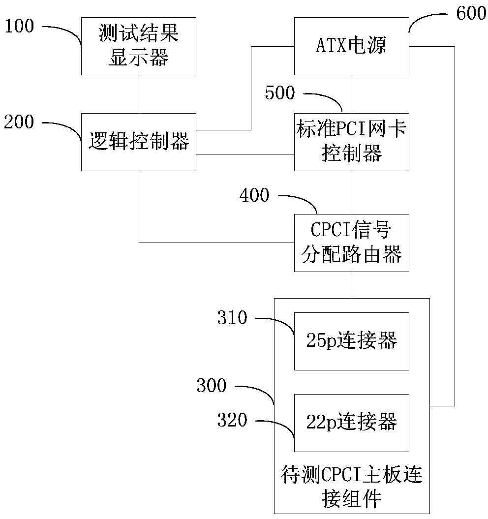
[0033] see figure 1 , a structural diagram of a CPCI bus testing device provided by an embodiment of the present invention. A kind of CPCI bus testing device that the embodiment of the present invention provides, comprises: test result display 100, logic controller 200, to-be-tested CPCI motherboard connection assembly 300, CPCI signal distribution router 400, standard PCI network card controller 500 and ATX power supply 600. The test device adopts the connection component of the CPCI motherboard to be tested to provide an external standard 6U CPCI slot for installing the CPCI motherboard to be tested. After completing the basic connection, start the test. for an intuitive display.

[0034] The logic controller 200 is connected with the ATX power supply 600, the standard PCI network card controller 500 and the CPCI signal distribution router 400 respectively, and the standard PCI network card controller 500, the CPCI signal distribution router 400, and the CPCI motherboard co...

Embodiment 2

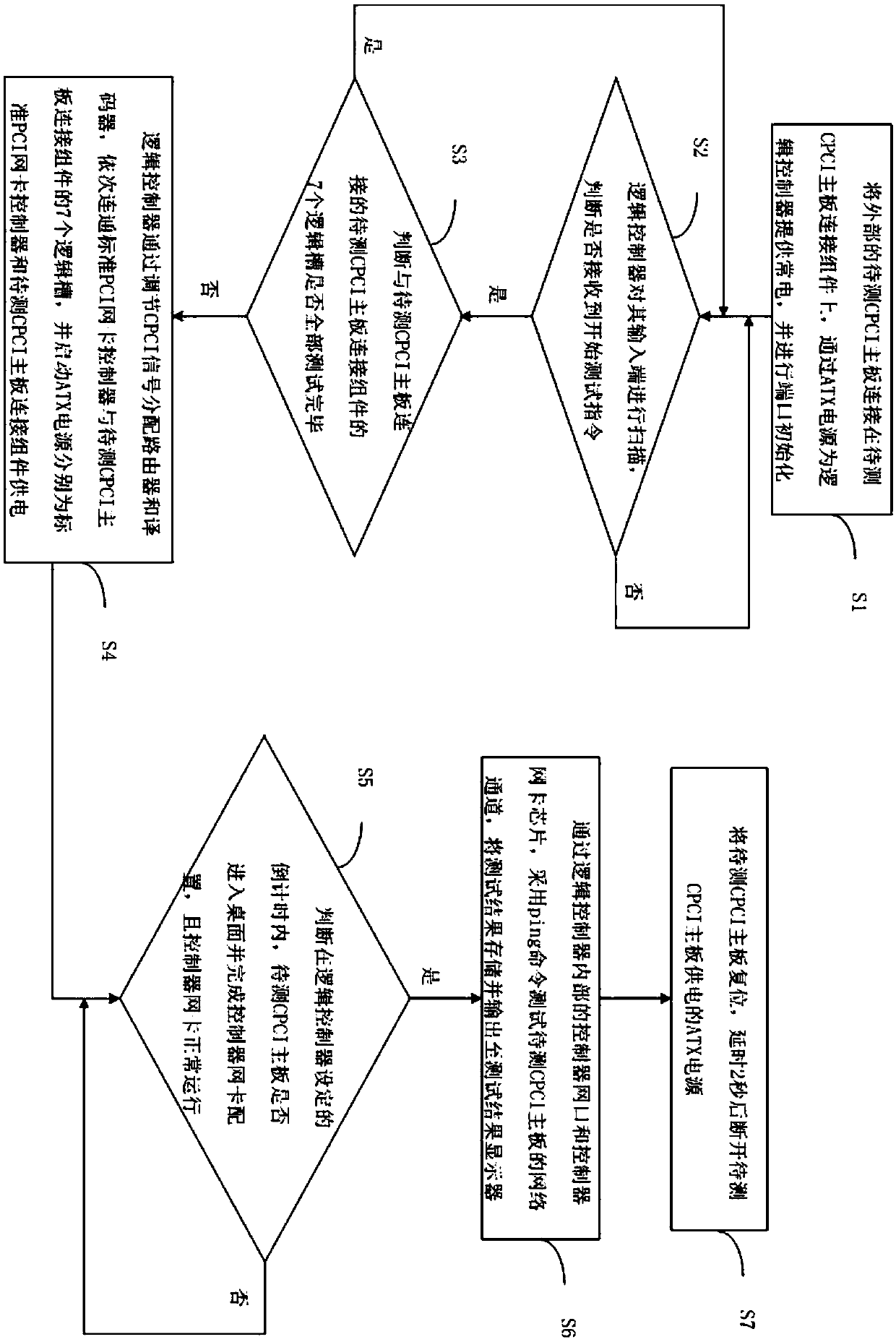
[0042] see figure 2 , a flowchart of a CPCI bus testing method provided by an embodiment of the present invention. A kind of CPCI bus testing method that the embodiment of the present invention provides, comprises:

[0043] Step 1: Connect the external CPCI motherboard to be tested to the CPCI motherboard connection component to be tested, provide constant power to the logic controller through the ATX power supply, and perform port initialization. The logic controller is the STM32F107VCT6 ARM microcontroller of ST Company, which is used to connect the standard PCI network card to the tested 6U CPCI motherboard in sequence, and is also used to store and display the test results on the test result display. Further, the logic controller includes a controller network port and a controller network card; the controller network port and the controller network card are connected to a standard PCI network card controller. Further, the connection components of the CPCI motherboard to...


PUM


Abstract

The invention provides a CPCI bus test device and method, which relates to the technical field of data transmission bus automation test. The device includes a test result display, a logic controller,a CPCI motherboard connection component to be tested, a CPCI signal distribution router, a standard PCI network card controller and an ATX power supply. The logic controller is connected to the ATX power supply, the standard PCI network card controller and the CPCI signal distribution router, the standard PCI network card controller, the CPCI signal distribution router, the CPCI motherboard connection assembly to be tested are connected sequentially, the ATX power supply is connected with the CPCI motherboard connection assembly to be tested and the standard PCI network card controller respectively, the CPCI motherboard connection assembly to be tested comprises a 25p connector and a 22p connector, and a test result display is connected with the logic controller. The technical scheme realizes the automatic test of the CPCI motherboard, improves the test efficiency of the CPCI motherboard, reduces the human cost of the test of the CPCI motherboard, and alleviates the technical problemsof low bus detection efficiency and high human cost of the existing CPCI motherboard.

Description

technical field [0001] The invention relates to the technical field of data transmission bus automation testing, in particular to a CPCI bus testing device and method. Background technique [0002] At present, all 6U CPCI motherboards contain CPCI bus functions, and support CPCI specifications, and the anti-vibration impact capability and reliable heat dissipation capability are enhanced, but the efficiency of testing the CPCI bus is low, especially in the case of mass production of motherboards with CPCI bus functions. The testers bring a lot of pressure, and the labor intensity is too high. The traditional test of the 6U CPCI bus function is to install 7 standard peripheral boards on the standard 6U CPCI backplane, and at the same time insert the tested CPCI main board into the main slot, and connect the monitor, keyboard and mouse to the main board. Then install the ATX power supply on the backboard, manually power on the tested CPCI motherboard, wait for the motherboard...

Claims


Application Information

Patent Timeline
Patent Type & Authority Applications(China)
IPC IPC(8): G06F11/26G06F11/22
CPCG06F11/221G06F11/26
Inventor 张德新
Owner TIANJIN EMBEDTEC
Learn More