Universal mold for forming of house prefabricated part laminated slab

A technology of prefabricated components and universal moulds, applied in the direction of forming surfaces, manufacturing tools, mold trays, etc., can solve the problem that a pair of forming casting molds do not have universal use requirements, cannot take advantage of the factory’s mass production advantages, and cannot meet the requirements of the relief slot Problems such as the laminated plate bottom plate, etc., achieve the effect of saving mold processing time, high mold assembly efficiency, and efficient side mold processing

Pending Publication Date: 2018-10-23
福建鸿生高科环保科技有限公司
View PDF1 Cites 7 Cited by
  • Summary
  • Abstract
  • Description
  • Claims
  • Application Information

AI Technical Summary

Problems solved by technology

[0004]When the above-mentioned casting mold is used, due to the different buildings, the size of the prefabricated laminated slab floor, as well as the spacing and arrangement of steel bars in the laminated slab floor are required It will be different. The relief slots in a pair of forming casting molds for the protruding steel joints cannot meet the needs of different laminated slabs. When plying the bottom plate, it is necessary to make multiple forming casting molds, the mold processing cycle is long, the production cost is high, the mold is not conducive to repeated use, and the advantages of mass production of the factory cannot be fully utilized, which is not conducive to further improving the production efficiency of prefabricated components

Method used


Image

  • Universal mold for forming of house prefabricated part laminated slab
  • Universal mold for forming of house prefabricated part laminated slab
  • Universal mold for forming of house prefabricated part laminated slab

Examples


Embodiment

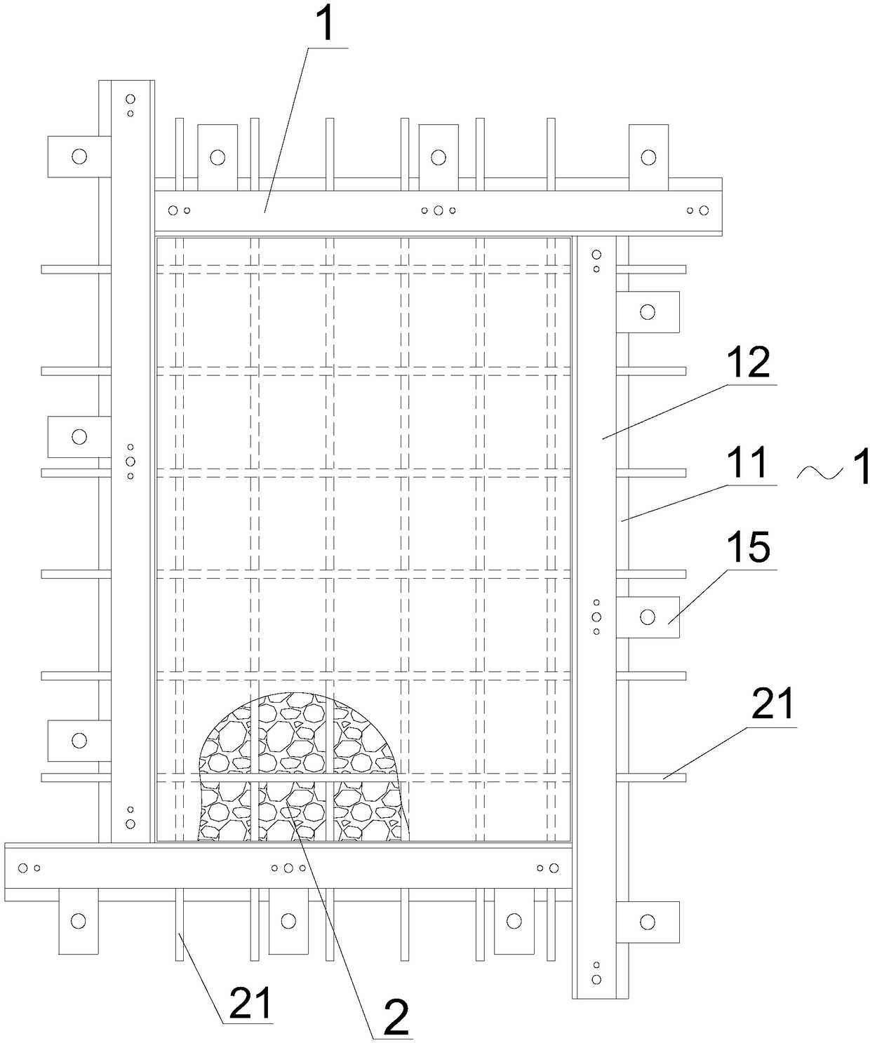
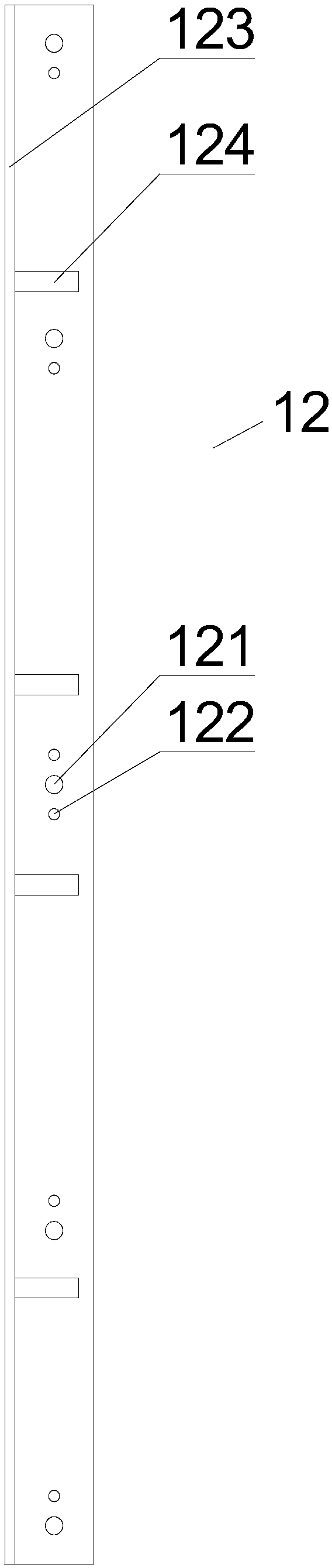
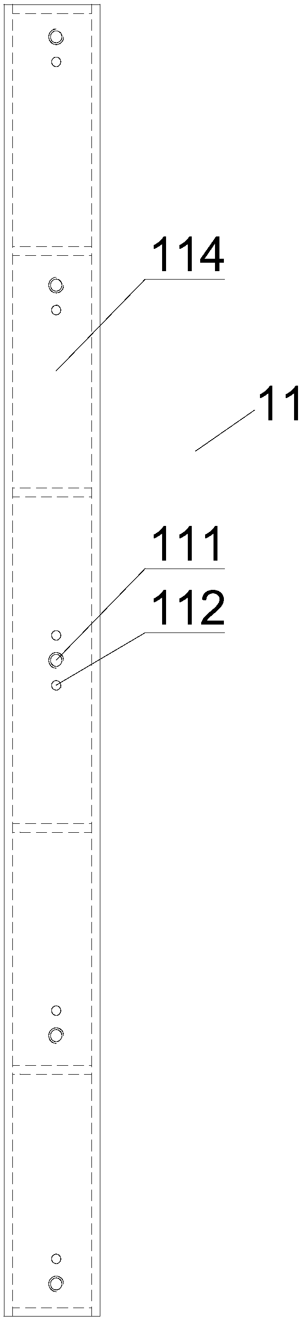
[0032] see Figure 1~5 As shown, a general-purpose mold for forming laminated panels of prefabricated building components according to the present invention includes four forming side mold assemblies 1, and the four forming side mold assemblies 1 are formed by two-by-two vertical intersecting and enclosing An outer frame that can be molded to make a prefabricated laminated plate bottom plate 2, each of the forming side mold assemblies 1 is provided with a bottom mold 11 and a side mold 12, and the cross-sectional width of the bottom mold 11 is greater than that of the side mold 12 Section width, the bottom mold 11 is fixedly arranged on the mold table 3, the side mold 12 is fixed on the bottom mold 11, an overhead gasket 13 and a sealing strip 14 are arranged between the bottom mold 11 and the side mold 12, and the The ends of the criss-crossing steel bars 21 in the prefabricated laminated slab bottom plate 2 respectively protrude from the gap between the bottom mold 11 and th...


PUM

PropertyMeasurementUnit
thicknessaaaaaaaaaa

Abstract

The invention relates to a universal mold for forming of a house prefabricated part laminated slab, and relates to the technical field of house prefabricated part production. An outer frame for forming a prefabricated laminated slab bottom plate is defined by four forming side mold assemblies, a bottom mold and a side mold are arranged in each forming side mold assembly, the bottom molds are fixedto a mold table, the side molds are fixed to the bottom molds, overhead gaskets and sealing strips are arranged between the bottom molds and the side molds, and criss-cross rebar ends in the prefabricated laminated slab bottom plate stretch out of the gaps between the bottom molds and the side molds. Each bottom plate is further provided with two or more fixing pressing plates, one ends of the fixing pressing plates are pressed on the upper surfaces of the bottom molds, and the other ends of the fixing pressing plates are fixed to the mold table through bolts. One forming side mold assembly can adapt to the rebar interval change in different prefabricated laminated slab bottom plates, the universality is good, the specifications of the forming side mold assemblies needed for production are greatly reduced, production and use are convenient, the assembly efficiency of the molds is high, demolding is convenient, and the large-scale production advantages of factories can be fully exerted.

Description

technical field [0001] The invention relates to the technical field of production of house prefabricated components, in particular to a general mold for forming laminated panels of house prefabricated components. Background technique [0002] With the continuous development of my country's economy and the gradual improvement of people's living standards, more and more prefabricated buildings have appeared on the market. Prefabricated buildings are more efficient than cast-in-place reinforced concrete prefabricated buildings and can speed up the construction progress. Laminated slab components are widely used in prefabricated buildings. Laminated slabs are building panels that combine prefabricated bottom slabs and cast-in-place concrete, that is, laminated slabs are integral floor slabs that are connected and laminated by prefabricated bottom slabs and cast-in-place concrete layers through truss bars. , the prefabricated bottom plate is used as the bottom form of the cast-in...

Claims


Application Information

Patent Timeline
Patent Type & Authority Applications(China)
IPC IPC(8): B28B7/00
CPCB28B7/0032B28B7/0002B28B7/0011B28B7/0055
Inventor 刘刚金旺洲
Owner 福建鸿生高科环保科技有限公司
Why Eureka
Try Eureka