Suspension system construction method for parameter observation of non-bearing synchronous reluctance motor

A technology of synchronous reluctance motor and motor parameters, applied in control systems, control generators, vector control systems, etc., can solve the problems of relying on motor suspension winding flux linkage identification accuracy, complex algorithms, affecting rotor suspension control accuracy, etc.

Active Publication Date: 2018-10-23
NANJING COLLEGE OF INFORMATION TECH
View PDF6 Cites 7 Cited by
  • Summary
  • Abstract
  • Description
  • Claims
  • Application Information

AI Technical Summary

Problems solved by technology

[0003] In order to realize the stable suspension of the rotor of the bearingless synchronous reluctance motor, the radial displacement of the rotor must be detected and closed-loop controlled. The sensor brings defects such as increased motor size, reduced motor reliability, and increased manufacturing costs.
A national invention patent (Patent No.: ZL201010583419.6) has been published on the rotor displacement soft measurement and suspension system construction method of the bearingless synchronous reluctance motor, but the accuracy of the rotor displacement detection method described in the patent is not good. High, completely dependent on the flux linkage identification accuracy of the motor suspension winding
Another national invention patent (patent number: ZL201010017952.6) on the control method of bearingless synchronous reluctance motor without dis

Method used


Image

  • Suspension system construction method for parameter observation of non-bearing synchronous reluctance motor
  • Suspension system construction method for parameter observation of non-bearing synchronous reluctance motor
  • Suspension system construction method for parameter observation of non-bearing synchronous reluctance motor

Examples


Embodiment Construction

[0090] In order to make the content of the present invention more obvious and understandable, further description will be made below in conjunction with the accompanying drawings and specific embodiments.

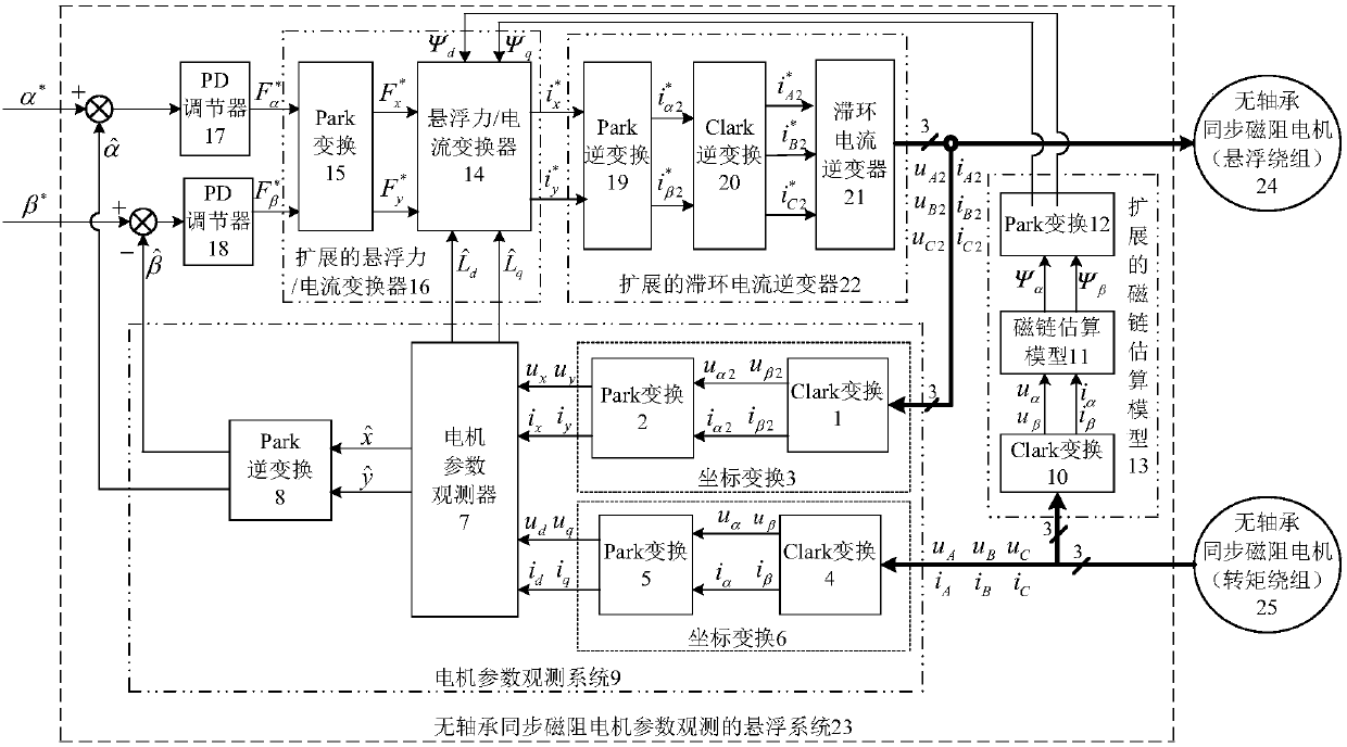
[0091] To construct a suspension system based on the parameter observation of a bearingless synchronous reluctance motor, a preferred embodiment of the present invention has a structural principle as figure 2 :

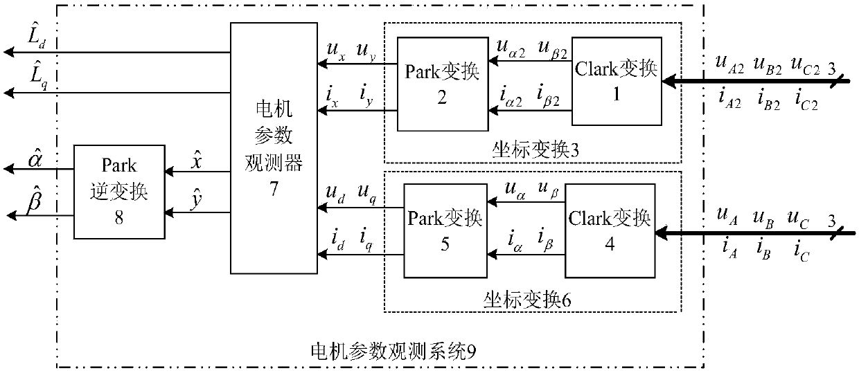
[0092] Construct the motor parameter observation system 9, combined with figure 1 , the motor parameter observation system is composed of two coordinate transformations 3 and 6, a motor parameter observer 7 and a Park inverse transformation 8, wherein a coordinate transformation 3 is composed of a Clark transformation 1 and a Park transformation 2, and a coordinate transformation 6 consists of a Clark transformation 4 and a Park transformation 5.

[0093] Detect and obtain the three-phase current and voltage of the suspension winding and torque winding of the mo...


PUM


Abstract

The invention discloses a suspension system construction method for parameter observation of a non-bearing synchronous reluctance motor. The method comprises: constructing a motor parameter observation system; detecting three-phase currents and voltages of a motor suspension winding and transmitting the three-phase currents and voltages into the input terminal of the motor parameter observation system; detecting the three-phase currents and voltages of the motor torque winding, sending the three-phase currents and voltages into an extended flux linkage estimation model, outputting a flux linkage observation value under a two-phase synchronous rotation coordinate by the extended flux linkage estimation model, and using the flux linkage observation value as one of input signals of an extended suspension force/current transformer; constructing the suspension force/current transformer and outputting a two-phase current reference value of a motor suspension winding by the extended suspension force/current transformer as an input signal of an extended hysteresis current inverter, providing power for the motor suspension winding by the hysteresis current inverter, generating an expected suspension force, and realizing `rotor displacement and inductance parameter observation of a controller motor under a non-displacement sensor. The constructed suspension system has advantages of quickresponse and excellent performance.

Description

technical field [0001] The invention relates to the technical field of AC motor control, in particular to a construction method of a bearingless synchronous reluctance motor suspension system based on motor parameter observation, which is suitable for the suspension operation of a bearingless synchronous reluctance motor without a displacement sensor under high-speed conditions. Background technique [0002] The bearingless synchronous reluctance motor is a set of suspension windings superimposed on the basis of the torque winding in the stator slot of the ordinary synchronous reluctance motor, which is used to generate a radial suspension force that supports the stable suspension of the rotor, and controls the current of the two sets of windings of the motor. It can control the speed of the motor and the suspension of the rotor at the same time. The bearingless synchronous reluctance motor has outstanding high quality: low noise, low power consumption, high speed, no lubric...

Claims


Application Information

Patent Timeline
IPC IPC(8): H02N15/00H02P21/00H02P21/24
CPCH02N15/00H02P21/0085H02P21/24
Inventor 张汉年鲍安平段向军茆建国胡鹏飞
Owner NANJING COLLEGE OF INFORMATION TECH
Why Eureka
Try Eureka