

Sputtering target for magnetic recording medium, and magnetic thin film
A sputtering target, non-magnetic technology, applied in the field of sputtering targets, can solve problems such as adhesion problems, and achieve the effects of improving device characteristics, improving yield, and reducing the amount of powder particles
- Summary
- Abstract
- Description
- Claims
- Application Information
AI Technical Summary
Problems solved by technology
Method used
Image

Examples
Embodiment 1~6
[0058] (Examples 1 to 6: non-magnetic phase C, etc.)
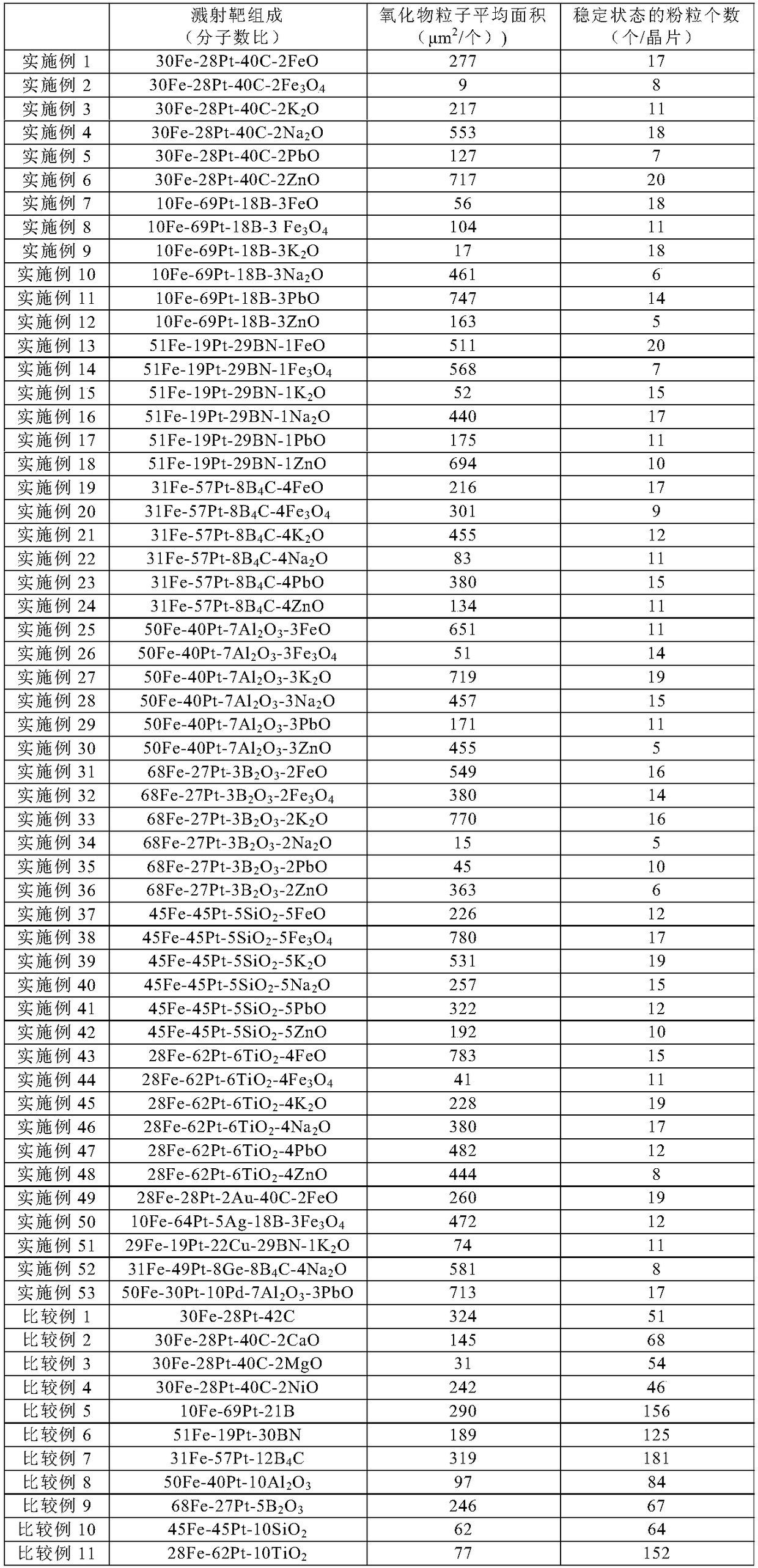
[0059] Prepare Fe powder and Pt powder as magnetic materials, prepare C powder as non-magnetic materials, prepare FeO powder, Fe 3 o 4 Powder, K 2 O powder, Na 2 O powder, PbO powder, and ZnO powder are used as low-viscosity oxides. Then, these powders were weighed to obtain the composition ratios described in Table 1.
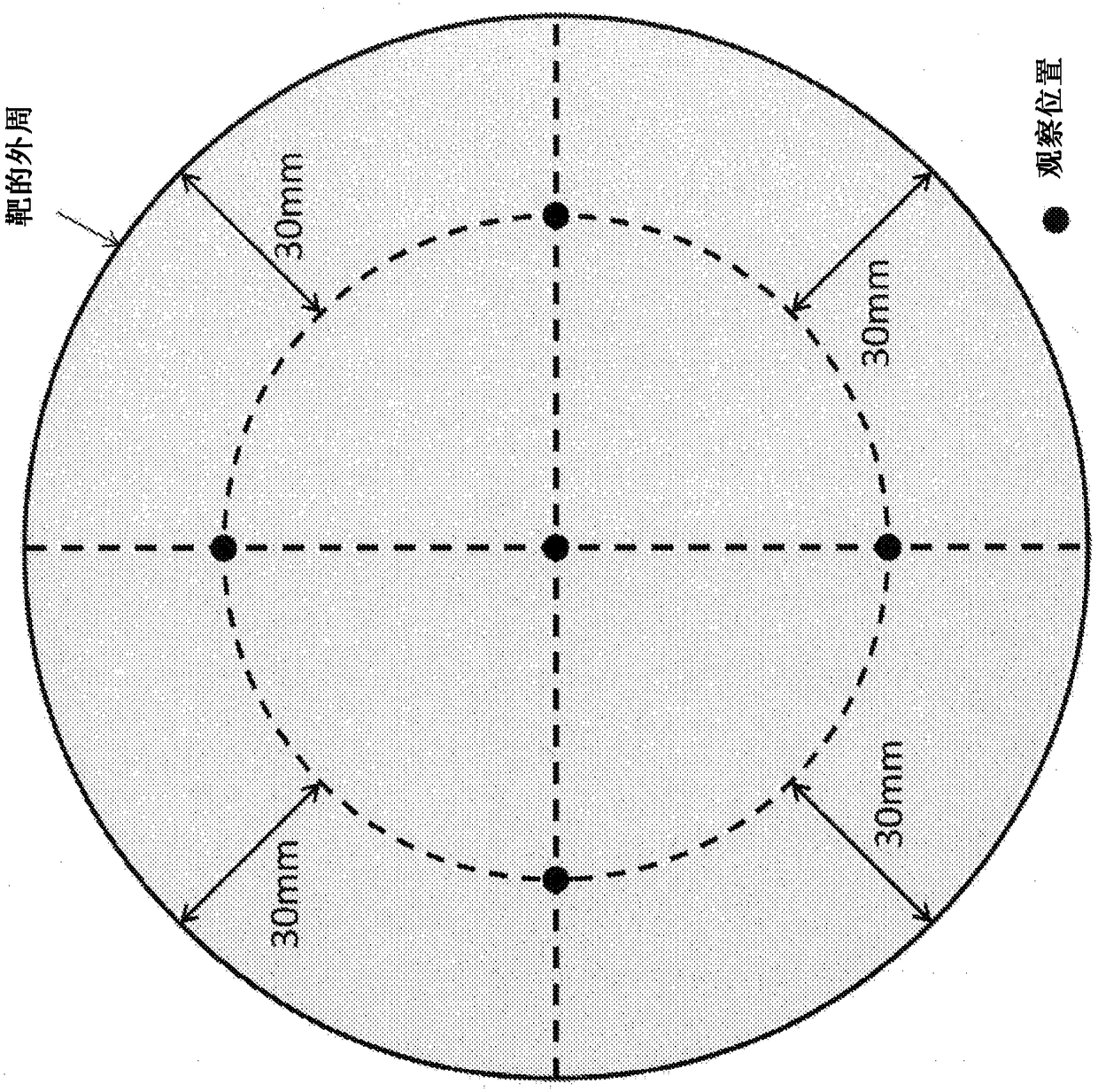
[0060] Next, for each of Examples 1 to 6, the weighed powders were placed in a ball mill pot with a capacity of 10 liters together with zirconia balls as grinding media, and mixed by rotating for 24 hours. Then, the mixed powder taken out from the ball mill was filled in a carbon mold with a diameter of 190 mm, and sintered by hot pressing. The conditions of the hot pressing were set to a vacuum atmosphere, a heating rate of 300° C. / hour, a holding temperature of 1050° C., a holding time of 2 hours, and pressurization at 30 MPa from the start of heating to the end of holding. After completion of hold...
Embodiment 7~12
[0065] (Examples 7 to 12: non-magnetic phase B, etc.)
[0066] Prepare Fe powder and Pt powder as magnetic materials, prepare B powder as non-magnetic materials, prepare FeO powder, Fe 3 o 4 Powder, K 2 O powder, Na 2 O powder, PbO powder, and ZnO powder were used as low-viscosity oxides, and these powders were weighed to obtain the composition ratios listed in Table 1. Then, for each of Examples 7 to 12, a sintered body was produced by the same method as in Examples 1 to 6. The cross-section of the obtained sintered body was observed with a microscope in the same manner as in Examples 1 to 6, and it was confirmed that the structure of the non-magnetic phase was dispersed in the magnetic phase. In addition, for each of Examples 7 to 12, the average area per one nonmagnetic particle was calculated in the same manner as in Examples 1 to 6. The results are shown in Table 1. Next, sputtering was performed in the same manner as in Examples 1 to 6 using each of the sintered bo...
Embodiment 13~18
[0067] (Examples 13 to 18: non-magnetic phase BN, etc.)
[0068] Prepare Fe powder and Pt powder as magnetic materials, prepare BN powder as non-magnetic materials, prepare FeO powder, Fe 3 o 4 Powder, K 2 O powder, Na 2 O powder, PbO powder, and ZnO powder were used as low-viscosity oxides, and these powders were weighed to obtain the composition ratios listed in Table 1. Then, for each of Examples 13 to 18, a sintered body was produced by the same method as that of Examples 1 to 6. The cross-section of the obtained sintered body was observed with a microscope in the same manner as in Examples 1 to 6, and it was confirmed that the structure of the non-magnetic phase was dispersed in the magnetic phase. Moreover, about each example of Examples 13-18, the average area per one nonmagnetic particle was calculated similarly to Examples 1-6. The results are shown in Table 1. Next, sputtering was performed in the same manner as in Examples 1 to 6 using each of the sintered bod...
PUM
| Property | Measurement | Unit |
|---|---|---|
| area | aaaaa | aaaaa |
| particle diameter | aaaaa | aaaaa |
| particle diameter | aaaaa | aaaaa |
Abstract
Description
Claims
Application Information