
Waste PCB board pyrolyzation device

A PCB board and pyrolysis technology, which is applied in the field of waste PCB board pyrolysis device, can solve the problems of secondary pollution, difficult rework, waste of non-condensable gas, etc., and achieve the effect of avoiding waste of resources and good pyrolysis effect

Inactive Publication Date: 2018-10-26
ANHUI SHENZE ELECTRONICS TECH
View PDF0 Cites 1 Cited by
  • Summary
  • Abstract
  • Description
  • Claims
  • Application Information

AI Technical Summary

Problems solved by technology

[0002] In the production process of PCB boards, due to the complex manufacturing process of PCB boards, the production process is a discontinuous assembly line form, and it is difficult to rework problems in the production process of PCB boards. Therefore, PCB board manufacturers will inevitably need to deal with scrapped products. PCB boards, the current treatment of waste PCB boards is mainly for the purpose of recycling metals, extracting metals by pyrometallurgy, hydrometallurgy, or separating and recycling metals by mechanical and physical methods. These methods will cause secondary pollution, while pyrolysis It is currently recognized that plastic substances undergo thermal decomposition reactions under anaerobic conditions, degrade polymers in plastics, and release volatile organic components from solid residues, and obtain pyrolysis oil that can be recycled after condensation. An effective method for resource recovery, but traditional pyrolysis devices are difficult to reuse non-condensable gases, and non-condensable gases are often wasted because they are difficult to collect. Therefore, a waste PCB that can better recycle pyrolysis products is needed Plate pyrolysis unit

Method used


Image

  • Waste PCB board pyrolyzation device
  • Waste PCB board pyrolyzation device

Examples


Embodiment Construction

[0020] Through the description of the embodiments below, the specific implementation of the present invention includes the shape, structure, mutual position and connection relationship between the various parts, the function and working principle of each part, the manufacturing process and the operation and use method of the various components involved. etc., to make further detailed descriptions to help those skilled in the art have a more complete, accurate and in-depth understanding of the inventive concepts and technical solutions of the present invention.

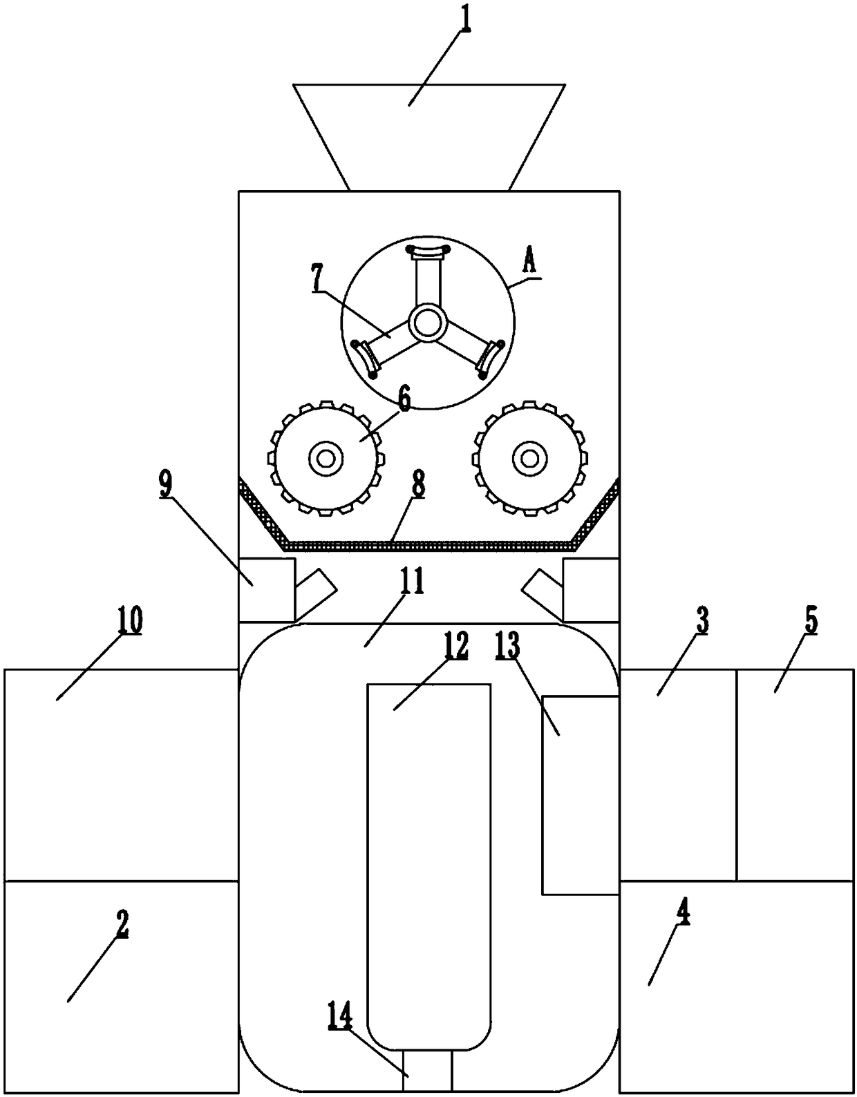
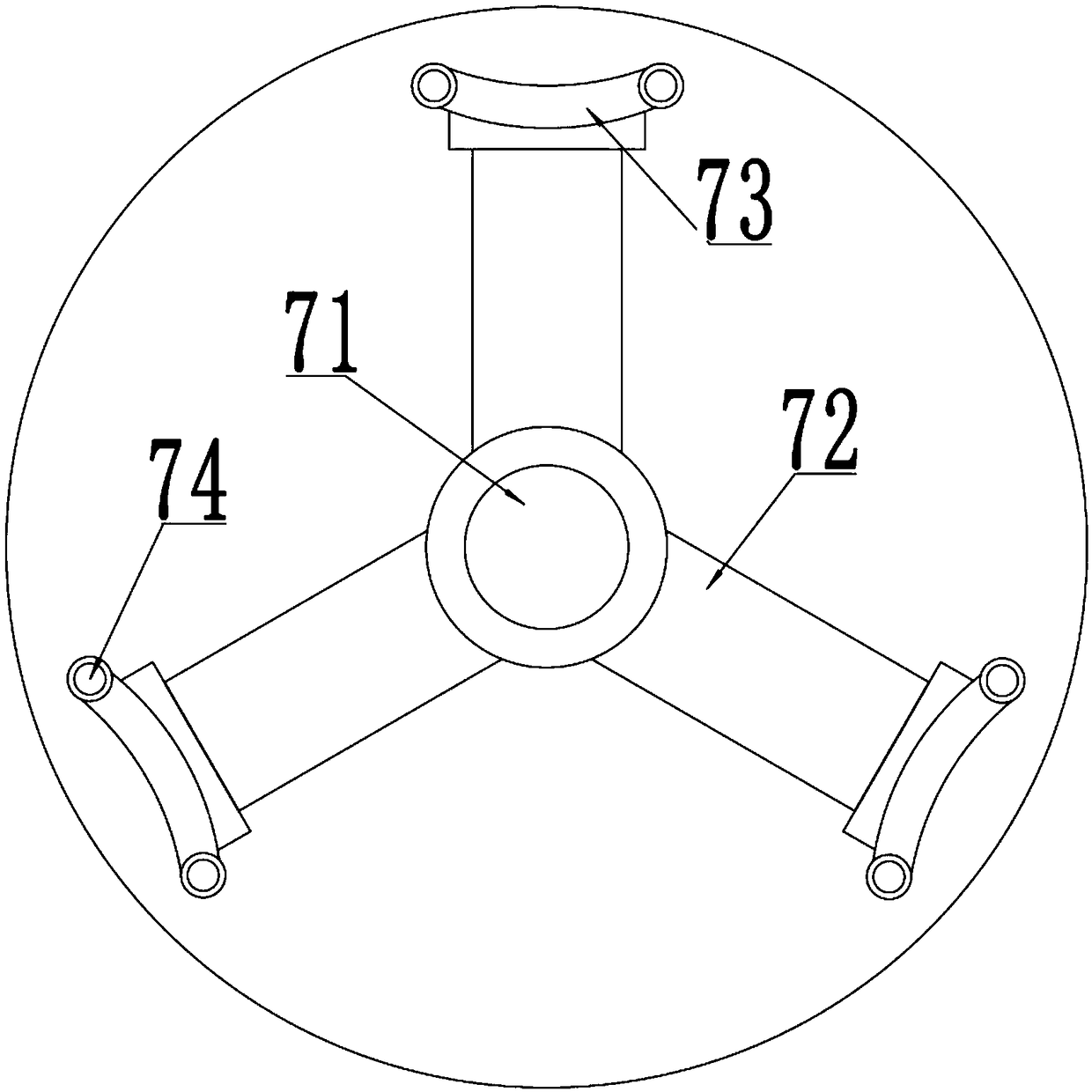
[0021] A waste PCB board pyrolysis device, including a feed port 1 and a crushing chamber, the feed port 1 is set above the crushing chamber, a heating chamber is connected to the bottom of the crushing chamber through a screening gate, and an inert gas supply device 2 is connected to the left side of the heating chamber A condenser 3 is connected to the right side of the heating chamber, a pyrolysis oil recovery device...


PUM


Abstract

The invention discloses a waste PCB board pyrolyzation device. The waste PCB board pyrolyzation device comprises a feeding hole and a crushing chamber, wherein the feeding hole is formed in the upperpart of the crushing chamber, a heating chamber is connected to the lower part of the crushing chamber through a screening gate, an inert gas supplying device is connected to the left side of the heating chamber, a condenser is connected to the right side of the heating chamber, a pyrolytic oil recycling device is connected to the lower part of the condenser, one end of a gas circulating device isconnected to the upper part of the condenser, and the other end of the gas circulating device is connected to the heating chamber. According to the waste PCB board pyrolyzation device, waste PCB boards can be crushed and pyrolyzed, solid products generated by pyrolyzation are remained in a quartz reaction pipe, a gas product generated by pyrolyzation is condensed into non-condensable gas and pyrolytic oil, the pyrolytic oil flows into the pyrolytic oil recycling device and is recycled, and the non-condensable gas enters the heating chamber and is taken as a combustion improver for the heatingchamber, so that the recycling is adequate, the wasting of resources is avoided, and secondary pollution is avoided.

Description

technical field [0001] The invention belongs to the technical field, and in particular relates to a waste PCB board pyrolysis device. Background technique [0002] In the production process of PCB boards, due to the complex manufacturing process of PCB boards, the production process is a discontinuous assembly line form, and it is difficult to rework problems in the production process of PCB boards. Therefore, PCB board manufacturers will inevitably need to deal with scrapped products. PCB boards, the current treatment of waste PCB boards is mainly for the purpose of recycling metals, extracting metals by pyrometallurgy, hydrometallurgy, or separating and recycling metals by mechanical and physical methods. These methods will cause secondary pollution, while pyrolysis It is currently recognized that plastic substances undergo thermal decomposition reactions under anaerobic conditions, degrade polymers in plastics, and release volatile organic components from solid residues, ...

Claims


Application Information

Patent Timeline
Patent Type & Authority Applications(China)
IPC IPC(8): C10G1/00B02C4/08B02C13/06B02C13/13B02C21/00B02C23/10
CPCC10G1/00B02C4/08B02C13/06B02C13/13B02C21/00B02C23/10B02C2201/06C10G1/008C10G2300/1003
Inventor 赵守江张琳张雷姜广彪胡洪波
Owner ANHUI SHENZE ELECTRONICS TECH
Learn More