Motor manufacturing method
A manufacturing method and iron core technology, applied in the manufacture of motor generators, stator/rotor bodies, electromechanical devices, etc., can solve the problems of low manufacturing efficiency, difficult manufacturing, high manufacturing cost, etc., achieve simple manufacturing process and improve manufacturing efficiency , the effect of flexible winding
- Summary
- Abstract
- Description
- Claims
- Application Information
AI Technical Summary
Problems solved by technology
Method used
Image

Examples
Embodiment 1
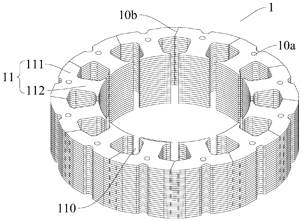
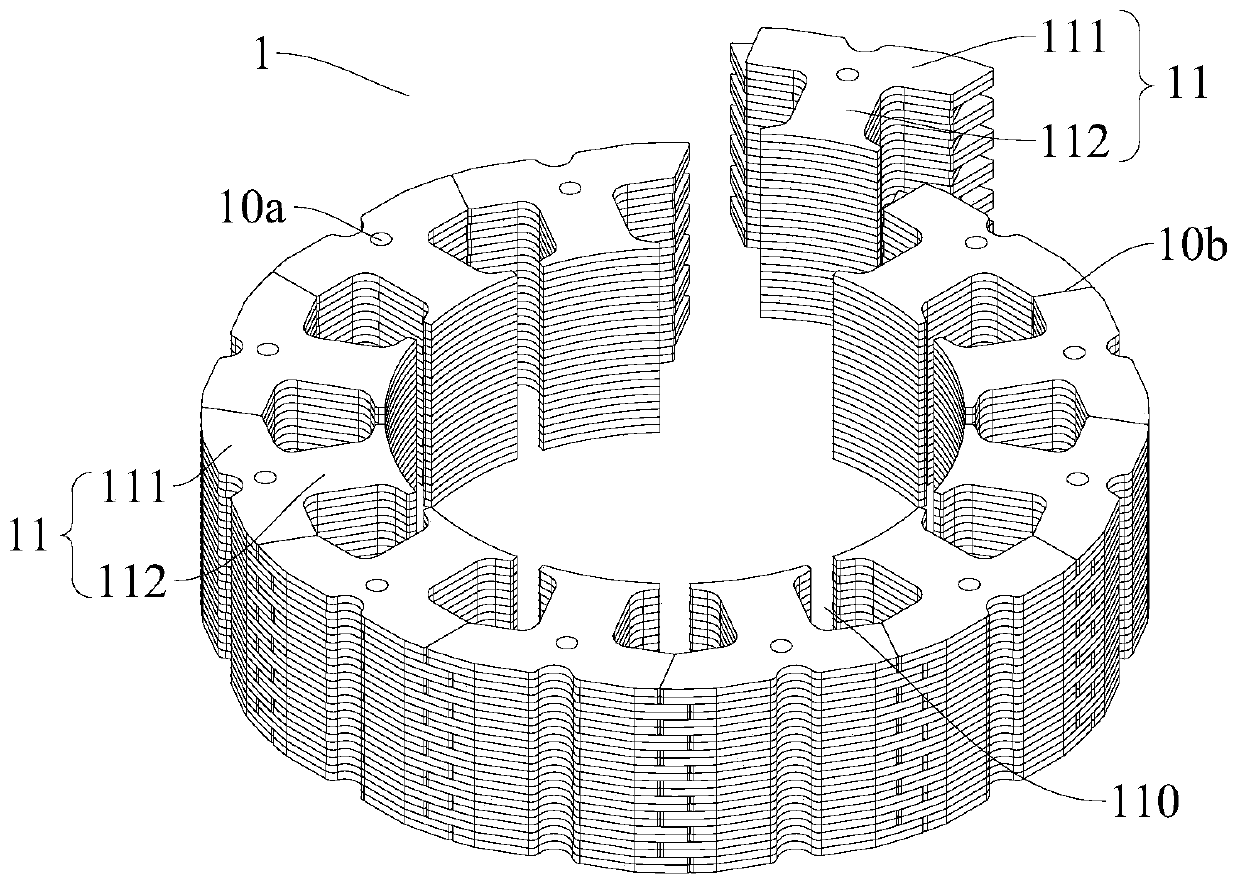
[0062] In this example, if Figure 1-Figure 9 As shown, the motor includes an iron core 1 and a winding. The iron core 1 can be roughly formed into a closed circular ring structure, and the iron core 1 includes 12 segmented iron cores 11 arranged in sequence along the circumferential direction. Each segmented iron core The core 11 includes a yoke portion 111 and a tooth portion 112 connected radially along the iron core 1, and an iron core slot 110 is formed between two adjacent tooth portions 112. In the circumferential direction of the iron core 1, each segmented iron core 11 The width of the yoke portion 111 is larger than that of the corresponding tooth portion 112 , and the winding is placed in the core slot 110 and wound on the tooth portion 112 of each segmented iron core 11 . Wherein, the rotor of the motor is located inside the stator, the iron core 1 is a stator iron core, and the outer peripheral wall of the iron core 1 is formed in a circular shape.
[0063] Such ...
Embodiment 2
[0070] Such as Figure 10 As shown, the structure of this embodiment is roughly the same as that of Embodiment 1, wherein the same components use the same reference numerals, the difference is that when the iron core 1 is in the unfolded state, the seven segmented iron cores 11 are distributed in a straight line 1. The five segmented iron cores 11 are distributed in an arc shape, and the iron core slots 110 between the five segmented iron cores 11 are set outward.
Embodiment 3
[0072] Such as Figure 11 As shown, the structure of this embodiment is substantially the same as that of Embodiment 2, wherein the same components use the same reference numerals, the difference is that when the iron core 1 is in the unfolded state, the nine segmented iron cores 11 are distributed in a straight line , The three segmented iron cores 11 are distributed in an arc shape, and the iron core slots 110 between the three segmented iron cores 11 are set outward.
PUM
 Abstract
Description
Claims
Application Information