Ventricular drainage positioning stent

A technology for positioning brackets and ventricular drainage, which is applied in the fields of suction equipment, medical science, and hypodermic injection equipment, etc. It can solve problems such as inaccurate measurement, damage to the patient's health, and hidden dangers to the patient's life safety, and achieve highly accurate drainage and effective use Good and accurate adjustment

Pending Publication Date: 2018-10-30
PEKING UNIV SHENZHEN HOSPITAL
View PDF11 Cites 3 Cited by
  • Summary
  • Abstract
  • Description
  • Claims
  • Application Information

AI Technical Summary

Problems solved by technology

[0005] In the above method of judging the position of the lowest point of the patient’s external auditory canal so as to locate the highest drainage height of the drainage tube, the use of visual inspection will make the measurement inaccurate, so that deviations will occur when subsequently adjusting the highest drainage height of the drainage tube fixed on the drainage bracket As a result, the highest drainage height of the corresponding drainage tube is too high or too low, which will cause hidden dangers to the patient's life safety. Although the measurement of the lowest point of the patient's external auditory canal can be measured accurately by using laser light horizontal irradiation, the laser light emitted by the corresponding laser light When the beam irradiates the patient's external auditory canal, it will generate radiation to the patient's external auditory canal, which will damage the patient's health and make the loss outweigh the gain. What's more, when adjusting the horizontal position of the corresponding laser light, there will still be laser beam irradiation emitted by the corresponding laser light. into the patient's eyes, causing blindness in the patient's eyes

Method used


Image

  • Ventricular drainage positioning stent
  • Ventricular drainage positioning stent
  • Ventricular drainage positioning stent

Examples


Embodiment Construction

[0054] The technical solution of the present invention will be described in detail below in conjunction with the accompanying drawings and specific embodiments, so as to understand the essence of the present invention more clearly and intuitively.

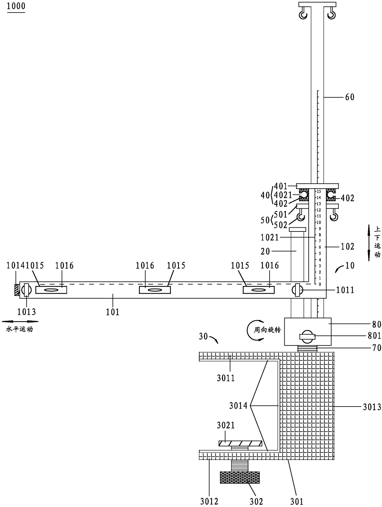
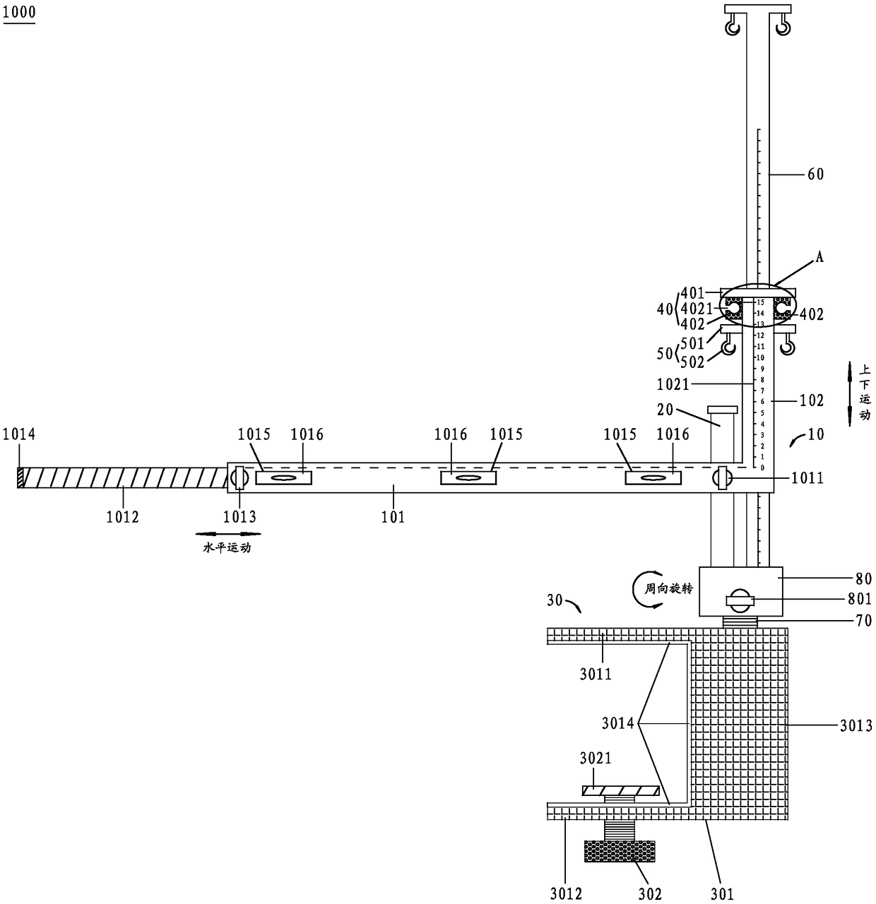
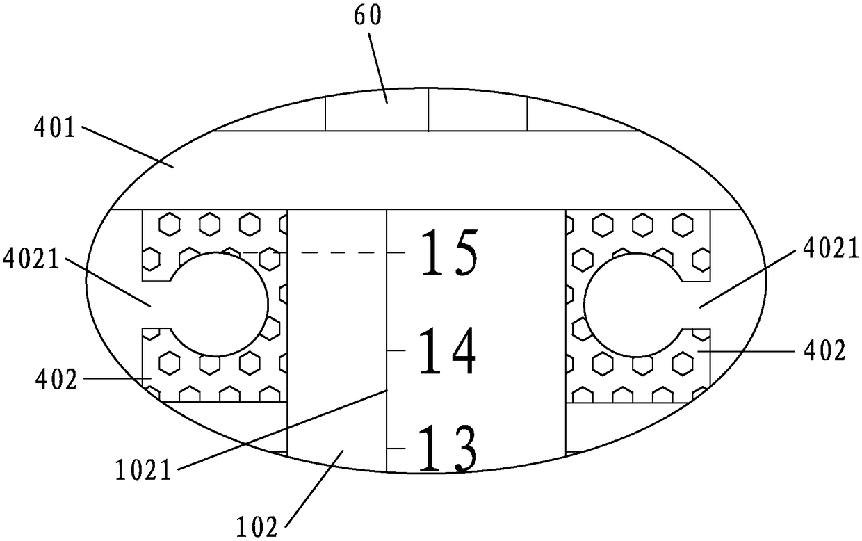
[0055] figure 1 It is a schematic diagram of the overall plane structure of the ventricular drainage positioning bracket of the present invention; figure 2 It is a diagram of the use state of the ventricular drainage positioning bracket of the present invention when the positioning rod A is adjusted up and the telescopic rod is stretched out; image 3 yes figure 2 Enlarged view of A in middle;

[0056] to combine figure 1 , figure 2 and image 3 shown;

[0057] A ventricular drainage positioning bracket 1000 provided by the present invention includes an L-shaped positioning mechanism 10, a guide column 20, and a fixing mechanism 30 for standing and fixing the guide column 20 above the bed edge of the hospital bed;

[0058...


PUM


Abstract

The invention discloses a ventricular drainage positioning stent which comprises an L-shaped positioning mechanism, a guide post and a fixing mechanism, wherein the fixing mechanism is used for fixingthe guide post on the bed edge of a hospital bed; the L-shaped positioning mechanism comprises a positioning rod A and a positioning rod B; a guide hole is vertically formed in the position, which isclose to the first end of the positioning rod A, of the bottom wall of the positioning rod A; the guide post penetrates through the guide hole, and the lower end of the guide post is connected with the fixing mechanism; a locking bolt A is arranged at the position, which is close to the first end of the positioning rod A, of the side wall of the positioning rod A; scale marks from 0cm to 15cm bytaking centimeter as the unit are arranged on the outer wall of the positioning rod B from bottom to top; the 0cm scale mark arranged on the outer wall of the positioning rod B is flush with the top wall of the positioning rod A; and when the locking bolt A is loosened, the height of the positioning rod A is adjustable, so that the height of the L-shaped positioning mechanism is adjustable. The ventricular drainage positioning stent has the effects that the positioning accuracy at the lowest point of the external auditory canal of a patient and positioning accuracy of the highest drainage position of a drainage tube can be ensured, and related nursing operation of ventricular drainage of the patient can be conveniently and rapidly performed, so that the ventricular drainage positioning stent disclosed by the invention is high in practicality and excellent in using effect.

Description

technical field [0001] The invention relates to the technical field of medical equipment, in particular to a ventricular drainage positioning bracket. Background technique [0002] Ventricular drainage is currently a simple and effective method for neurosurgery to treat ventricular hemorrhage and hydrocephalus and reduce intracranial pressure. It has a significant effect in the treatment of intracranial pressure reduction in critically ill patients such as drainage of ventricular hemorrhage and prevention of hydrocephalus. Patients after craniocerebral surgery often need to indwell a ventricular drainage tube. The height of the drainage tube must be adjusted at any time according to the patient's condition, the properties of the drainage fluid, and the intracranial pressure. Therefore, the nursing staff should pay special attention to the height of the drainage device. [0003] The quality of drainage care will be directly related to the success or failure of the operation ...

Claims


Application Information

Patent Timeline
Patent Type & Authority Applications(China)
IPC IPC(8): A61M1/00A61G13/10
CPCA61G13/10A61M1/74A61M1/84
Inventor 赖文娟
Owner PEKING UNIV SHENZHEN HOSPITAL
Why Eureka
Try Eureka