
Forging method capable of avoiding general looseness of hollow part forged through continuous casting blank with small deformation amount

A technology of continuous casting blanks and hollow parts, which is applied in the direction of manufacturing tools, forging/pressing/hammer devices, forging/pressing/hammering machinery, etc., and can solve the problem of reducing the deformation of the core and increasing the deformation of the outer metal, etc. problems, to achieve long service life, improve production efficiency, and reduce overall production costs

Inactive Publication Date: 2018-11-02
HENAN ZHONGYUAN SPECIAL STEEL EQUIP MFG CO LTD
View PDF5 Cites 3 Cited by
  • Summary
  • Abstract
  • Description
  • Claims
  • Application Information

AI Technical Summary

Problems solved by technology

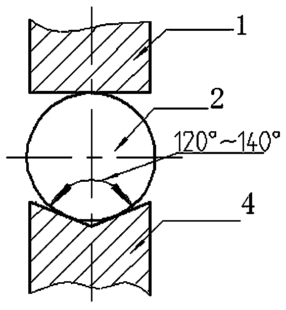
[0003] The object of the present invention is to overcome the deficiencies in the prior art and provide a special upper flat and lower V anvil forging, which increases the deformation of the outer layer of the forging and relatively reduces the deformation of the core, which is beneficial to corrugating rolls. This kind of hollow product is generally loose and qualified, and greatly improves production efficiency and reduces production costs. The small deformation improves the forging method of continuous casting slab forging hollow parts that are generally loose. In the case of insufficient deformation, special upper flat, The lower V anvil forging replaces the upper and lower flat anvil forging, changes the stress state of the blank and the flow direction of the metal, changes the deformation characteristics of the metal, and increases the deformation of the outer layer of metal, so as to achieve the purpose of improving the general looseness of the forging.

Method used


Image

  • Forging method capable of avoiding general looseness of hollow part forged through continuous casting blank with small deformation amount
  • Forging method capable of avoiding general looseness of hollow part forged through continuous casting blank with small deformation amount
  • Forging method capable of avoiding general looseness of hollow part forged through continuous casting blank with small deformation amount

Examples


Embodiment 1

[0020] Example 1: Example of corrugated roll forging:

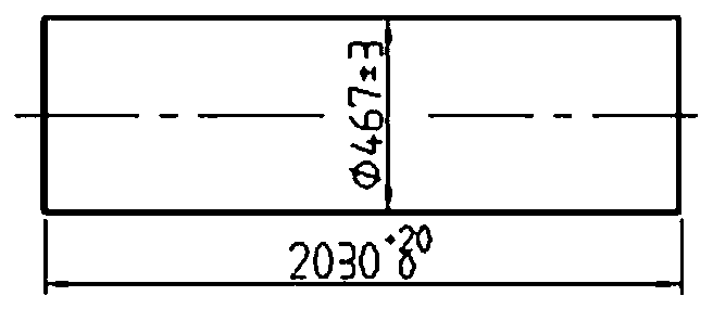
[0021] Take a corrugated roll of φ452mm (outer circle size) × φ300mm (inner hole size) × 2020mm (length size) as an example, for analysis, the forging picture is as follows image 3 (The unit of drawing size is mm).

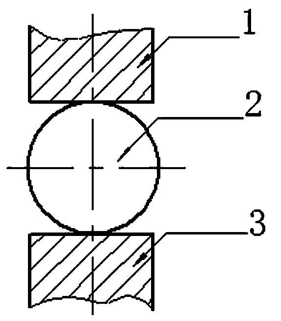
[0022] Such as Figure 4 As shown, in the traditional forging method using upper and lower flat anvils, for the φ800mm continuous casting billet 2, the 500mm wide upper flat anvil 1 and the lower flat anvil 3 are directly drawn and forged to φ500mm. The deformation diagram of the forging is shown in 4. by Figure 4 It can be seen that when the φ800mm continuous casting billet hydraulic press is deformed to φ500mm and forged with 500mm wide upper and lower flat anvils, the relative feed rate is relatively large (l i / h i >1), the deformation zone presents a single drum shape. This forging method has a large core deformation and can forge through, which is conducive to the compaction of the core. However, the side s...


PUM


Abstract

The invention relates to a forging method capable of avoiding general looseness of a hollow part forged through a continuous casting blank with small deformation amount. Under the insufficient deformation amount, special upper flat and lower V anvil forging is adopted to replace upper and lower flat anvil forging, the stress state of the blank and the flowing direction of metal are changed, the metal deforming characteristics are changed, and the outer layer metal deforming amount is increased; the continuous casting blank is heated and then fed into an oil press machine, the oil press machineadopts an upper flat and lower V anvil for forging, a precision forging machine is adopted for forging forming, after forging, annealing, inspection, ultrasonic flaw detection and discharging are carried out, through the forging method, general looseness of hollow part products like a corrugated roller produced by the continuous casting blank is avoided, production efficiency is improved, comprehensive production cost is reduced, and the product quality stability is high.

Description

Technical field [0001] The invention belongs to the technical field of forging, and specifically relates to a method of replacing the upper and lower flat anvil forging with special upper and lower V anvils under the condition of insufficient deformation, changing the stress state of the blank and the flow direction of the metal, and changing the metal The deformation characteristics of the outer layer metal are increased, and the small deformation amount improves the generally loose forging method of continuous casting blank forging hollow parts. Background technique [0002] At present, the production habit of continuous casting billet forgings is to use upper and lower flat anvils forging. However, due to the poor internal compactness of continuous casting billet, and the small deformation of hydraulic press and large relative feed, the general looseness of forgings is extremely low. In order to improve the qualification rate, the upsetting process is increased in the producti...

Claims


Application Information

Patent Timeline
Patent Type & Authority Applications(China)
IPC IPC(8): B21J5/00B21J5/06B21J13/06
CPCB21J5/002B21J5/06B21J13/06
Inventor 叶玉娟高全德刘新平赵东
Owner HENAN ZHONGYUAN SPECIAL STEEL EQUIP MFG CO LTD
Learn More