Heat-dissipating and rolling device for composite cloth material

A technology of rolling equipment and cloth, which is applied in the field of composite cloth heat dissipation and winding equipment, can solve the problems of low work efficiency, poor work continuity, and large space occupation, and achieve the effects of accelerating heat loss, increasing temperature difference, and accelerating heat absorption Effect

Inactive Publication Date: 2018-11-02
颜培吉 +2
View PDF7 Cites 8 Cited by
  • Summary
  • Abstract
  • Description
  • Claims
  • Application Information

AI Technical Summary

Problems solved by technology

[0009] The existing composite fabric will cool the fabric after hot pressing to prevent the fabric from deforming after winding. The existing composite fabric cooling equipment is expensive, not practical, unscientific in design, cumbersome in operation, and high in maintenance costs. , large volume, large space occupation, unstable work performance, low work efficiency, poor work continuity, etc.

Method used


Image

  • Heat-dissipating and rolling device for composite cloth material
  • Heat-dissipating and rolling device for composite cloth material
  • Heat-dissipating and rolling device for composite cloth material

Examples


Embodiment Construction

[0028] The following will clearly and completely describe the technical solutions in the embodiments of the present invention with reference to the accompanying drawings in the embodiments of the present invention. Obviously, the described embodiments are only some, not all, embodiments of the present invention.

[0029] In describing the present invention, it should be understood that the terms "upper", "lower", "front", "rear", "left", "right", "top", "bottom", "inner", " The orientation or positional relationship indicated by "outside", etc. is based on the orientation or positional relationship shown in the drawings, and is only for the convenience of describing the present invention and simplifying the description, rather than indicating or implying that the referred device or element must have a specific orientation, so as to Specific orientation configurations and operations, therefore, are not to be construed as limitations on the invention.

[0030] refer to Figure ...


PUM


Abstract

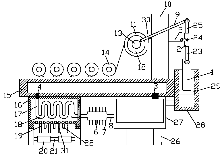
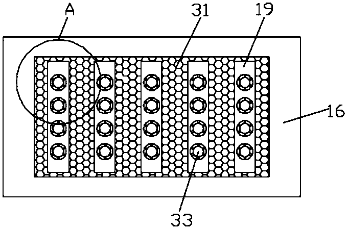
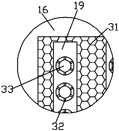
The invention discloses a heat-dissipating and rolling device for a composite cloth material. The heat-dissipating and rolling device for the composite cloth material comprises a worktable. A supporting pole is fixedly connected to the upper end of the worktable. A cloth rolling device is fixedly connected to the right side wall of the supporting pole. A reciprocating device is fixedly connected to the left side of the supporting pole. According to the heat-dissipating and rolling device for the composite cloth material, the rotation of a winding roller drives a piston and a cylinder barrel totransit, with pressure, cooling liquid into a heat-dissipating cavity to perform preliminary heat dissipation. Cooling fins arranged on the outer surface of the heat-dissipating cavity can accelerateheat dissipation of the cooling liquid. A heat-dissipating tube, a heat-conducting plate, first heat-dissipating plates, second heat-dissipating plates and heat-dissipating fans are arranged to carryout further heat dissipation on the cooling liquid. Phase transformation occurs when heat-conducting parts in the first heat-dissipating plates and the second heat-dissipating plates and phase changematerials arranged in the heat-conducting parts are heated, and heat dissipation on the heat-conducting plate is accelerated. Temperature difference between the heat-conducting plate and the coolingliquid is increased. Thus, heat absorption of the heat-conducting plate is further accelerated. A coil disc do reciprocating motion, and thus the cooling liquid in the heat-dissipating and rolling device for the composite cloth material is kept flowing without external power supply. The heat-dissipating and rolling device for the composite cloth material saves energy and protects environment.

Description

technical field [0001] The invention relates to the technical field of textile equipment, in particular to a heat-dissipating winding equipment for composite cloth. Background technique [0002] Composite fabric is a new type of material formed by bonding one or more layers of textile materials, non-woven materials and other functional materials. Suitable for making sofas, clothing and other textiles, it is one of the indispensable fabrics for people's home life. [0003] Composite fabrics apply "new synthetic fiber" high-tech and new materials, and have many excellent properties (compared with ordinary synthetic fibers), such as the performance of the fabric is fine and clean, delicate, elegant, warm, and the appearance of the fabric is plump, windproof and breathable. It has a certain waterproof function, and its main features are warmth retention and good air permeability. Another feature of this fabric is: good wear resistance, microfiber fabrics are soft, breathable, ...

Claims


Application Information

Patent Timeline
Patent Type & Authority Applications(China)
IPC IPC(8): B65H18/10B65H20/02
CPCB65H18/10B65H20/02B65H2301/5144B65H2701/174
Inventor 颜培吉李爱华刘亚娜
Owner 颜培吉
Why Eureka
Try Eureka