Electric heating Stirling engine
A Stirling engine and electric heating technology, which is applied to hot gas variable displacement engine devices, machines/engines, mechanical equipment, etc., can solve the problems of operator burns, inability to transfer all heat, loss, etc., and achieve the effect of improving efficiency
- Summary
- Abstract
- Description
- Claims
- Application Information
AI Technical Summary
Problems solved by technology
Method used
Image

Examples
Embodiment 1
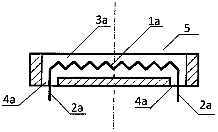
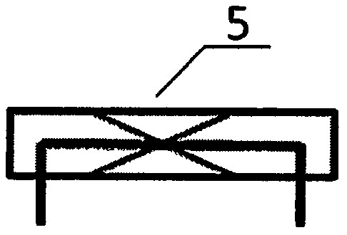
[0027] Figure 5 It is a diagram showing an Alpha (α) Stirling engine with a disc-shaped electric heating device inside the cavity. Flywheel 8 is fixedly connected with crankshaft 9, and cylinder 20, cylinder 22 and connecting hole 24 communicate and form cavity. Inside the cylinder 20 is arranged an airtight sliding piston 21 , which is hingedly connected to the crankshaft 9 via the connecting rod 10 . A disc-shaped electric heating device 5 is arranged at the inner bottom of the cylinder 20, and the two ends of the resistance wire are drawn out of the cylinder through an electrical insulating material tube 13, and the bottom of the cylinder is airtight. A thermal insulation material 12 is provided at the outer bottom of the cylinder 20 to prevent heat from radiating outward from the bottom of the cylinder 20 . A cooler 7 is provided outside the cylinder 22 . Inside the cylinder 22 is arranged an airtight sliding piston 23 , which is hingedly connected to the crankshaft 9 ...
Embodiment 2
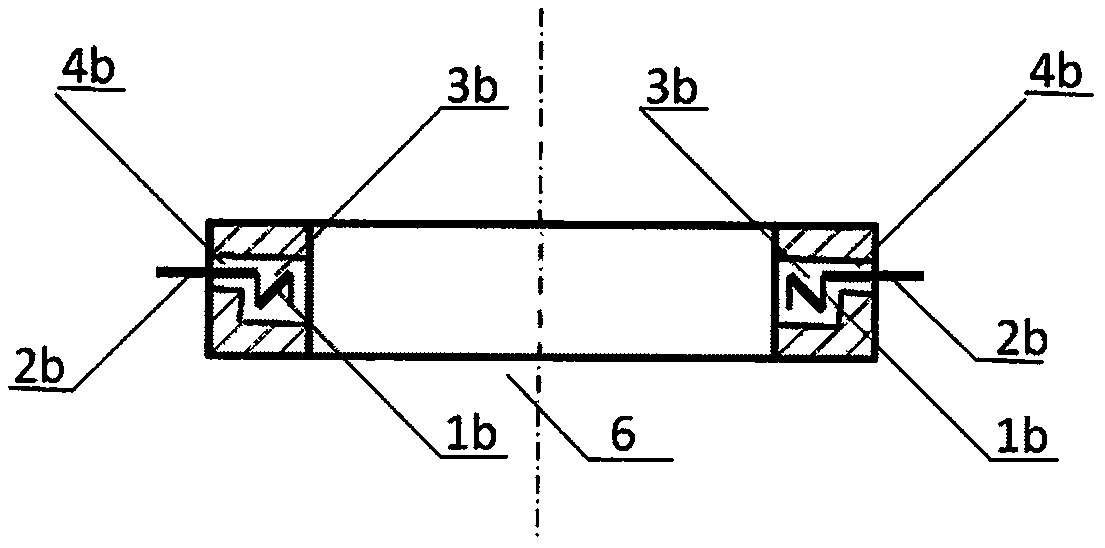
[0029] Image 6 It is a diagram showing an Alpha (α) Stirling engine with an annular electric heating device outside the cavity. Flywheel 8 is fixedly connected with crankshaft 9, and cylinder 20, cylinder 22 and connecting hole 24 communicate and form cavity. Inside the cylinder 20 is arranged an airtight sliding piston 21 , which is hingedly connected to the crankshaft 9 via the connecting rod 10 . An annular electric heating device 6 is arranged on the outer bottom of the cylinder 20 . A thermal insulation material 12 is arranged outside the annular electric heating device 6 to prevent heat from dissipating outward from the bottom of the cylinder 20 . Inside the cylinder 22 is arranged an airtight sliding piston 23 , which is hingedly connected to the crankshaft 9 via the connecting rod 11 . A cooler 7 is provided outside the cylinder 22 . The phase difference of the two cranks on the crankshaft 9 corresponding to the connecting rod 10 and the connecting rod 11 is 90 de...
Embodiment 3
[0031] Figure 7 It is a diagram showing a Beta (β) type Stirling engine with a disc-shaped electric heating device inside the cavity. Flywheel 8 is fixedly connected with crankshaft 9, and cylinder 34 is a cavity, and the piston 30 with the air-tight sliding of slideway hole 32 is set in the upper part of cylinder, and this piston is connected with crankshaft by connecting rod 10 hinges. A gas distribution piston 31 is arranged in the middle and lower part of the cylinder. There is a gas lubrication gap between the gas distribution piston and the cylinder. A shaft rod 33 is arranged on the upper part of the piston. Connecting rod 11 is hingedly connected, and this connecting rod top is hingedly connected with crankshaft 9, is airtight sliding between this shaft rod and this slideway hole. A disc-shaped electric heating device 5 is arranged at the inner bottom of the cylinder, and the two ends of the resistance wire are drawn out of the cylinder through an electric insulating...
PUM
 Abstract
Description
Claims
Application Information
 - R&D
- Intellectual Property
- Life Sciences
- Materials
- Tech Scout
- Unparalleled Data Quality
- Higher Quality Content
- 60% Fewer Hallucinations
Browse by: Latest US Patents, China's latest patents, Technical Efficacy Thesaurus, Application Domain, Technology Topic, Popular Technical Reports.
© 2025 PatSnap. All rights reserved.Legal|Privacy policy|Modern Slavery Act Transparency Statement|Sitemap|About US| Contact US: help@patsnap.com