
Minitype compressor with built-in liquid reservoir

A technology for a compressor and a liquid accumulator, applied in the field of compressors, can solve the problems of inconvenient disassembly and assembly, maintenance of the whole machine, small space position, poor welding, etc., and achieves the advantages of small space installation, compact internal structure, and reduced installation procedures. Effect

Pending Publication Date: 2018-11-02
GUANGZHOU DESHAN CNC TECH CO LTD
View PDF6 Cites 4 Cited by
  • Summary
  • Abstract
  • Description
  • Claims
  • Application Information

AI Technical Summary

Problems solved by technology

However, the separate external structure of the liquid reservoir occupies a large space, which is not conducive to installation in a small space, and there are many welding positions for the connecting pipe, and the space is small, the process is difficult, and poor welding is prone to occur
In addition, the inlet / outlet of the refrigerant is connected by welding, with many and complicated processes, and it is not easy to disassemble and maintain the whole machine

Method used


Image

  • Minitype compressor with built-in liquid reservoir
  • Minitype compressor with built-in liquid reservoir
  • Minitype compressor with built-in liquid reservoir

Examples


Embodiment Construction

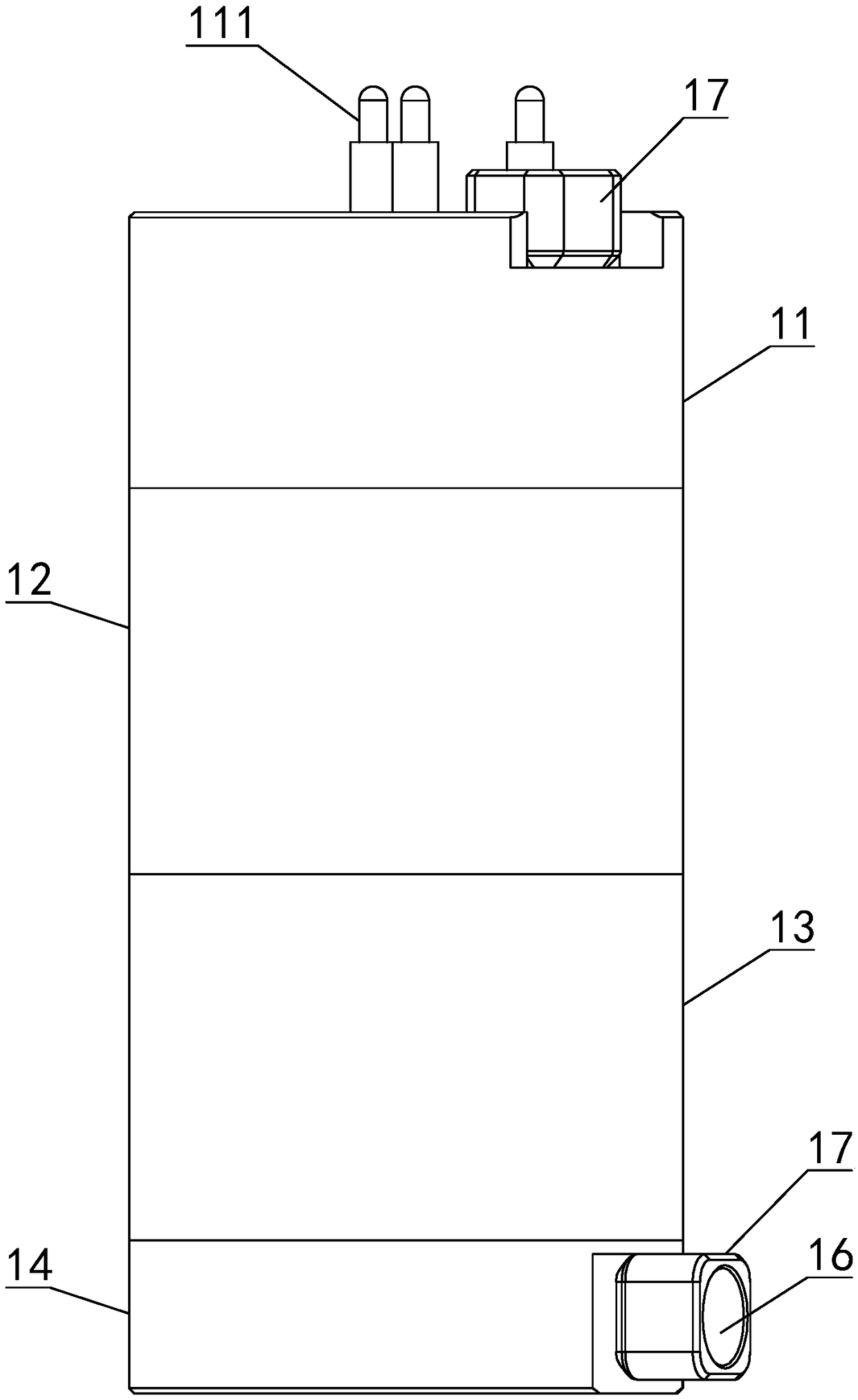
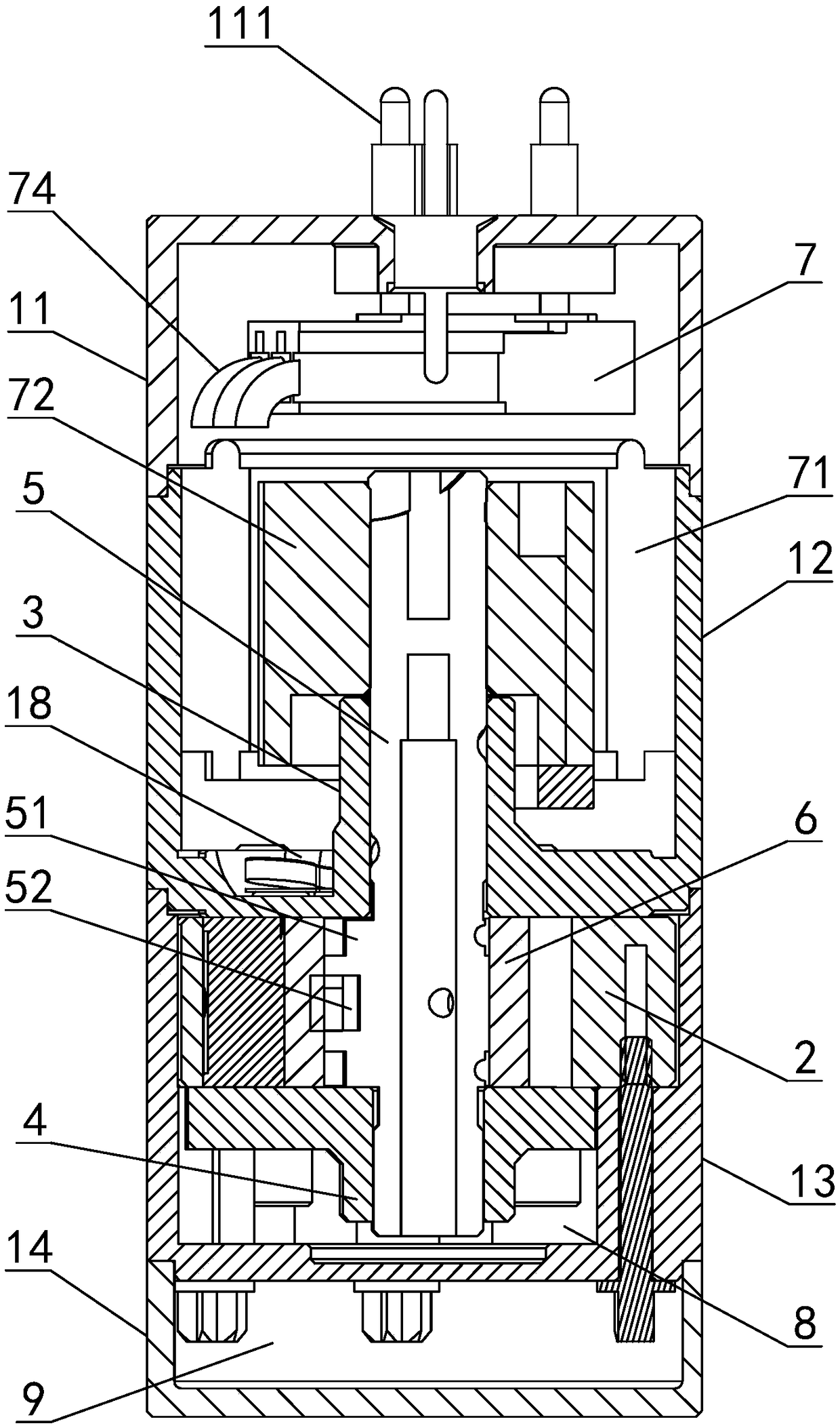
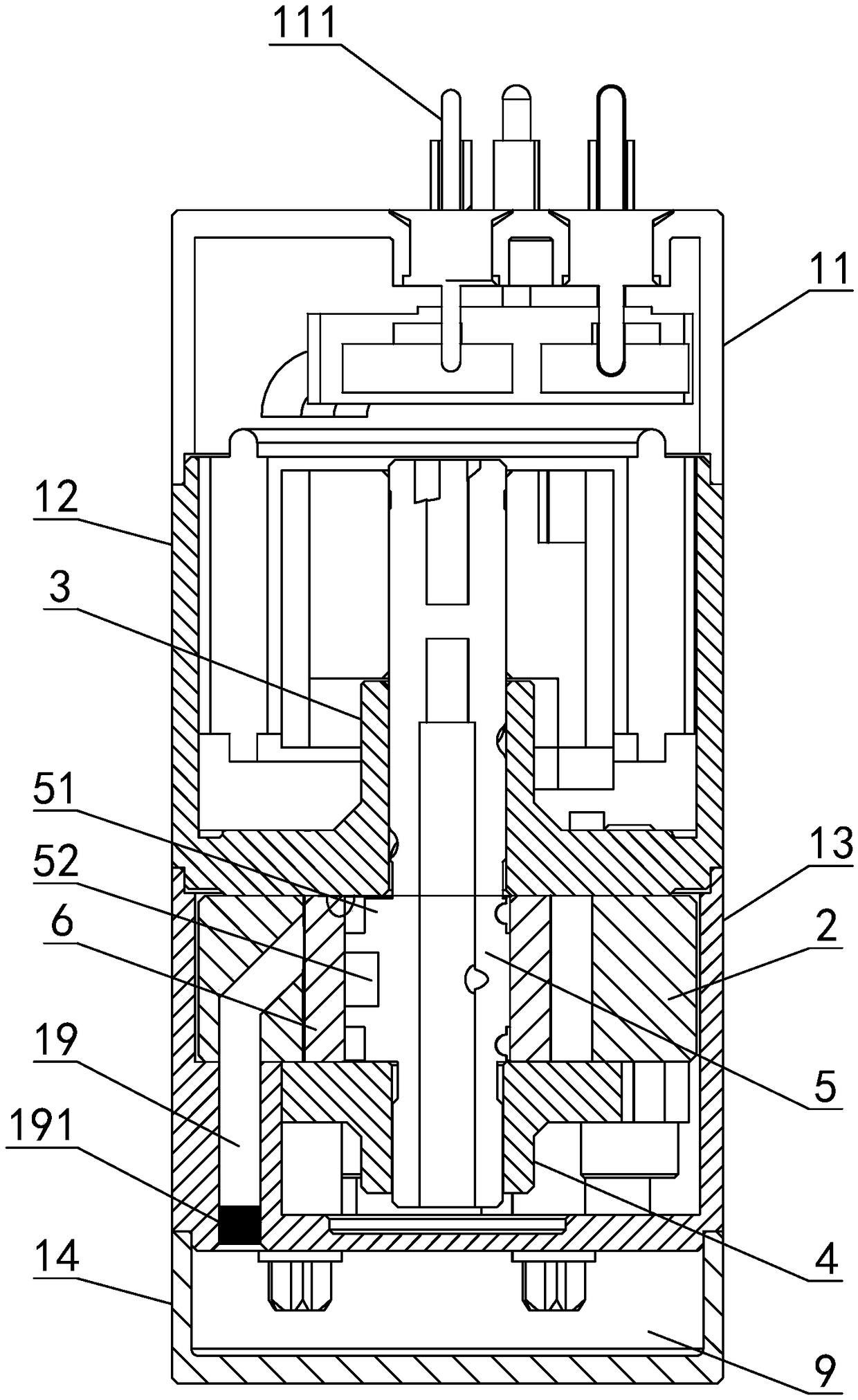
[0021] refer to Figure 1 to Figure 6 , the present invention is a micro-compressor with a built-in liquid accumulator, including a compressor main body, a cylinder 2, a main bearing 3, an auxiliary bearing 4, a crankshaft 5, a piston 6 and a motor 7 are installed in the compressor main body, and the compressor main body includes The high-pressure end cover 11, the main body frame 12, the compression chamber shell 13, and the low-pressure end cover 14 are sequentially matched and connected from top to bottom. A low-pressure refrigerant inlet 16, a high-pressure refrigerant outlet 15 and a low-pressure refrigerant inlet 16 are connected with flared copper tubes, and quick-connect nuts 17 are pre-installed on the copper tubes. The oil sump 8 is to store lubricating oil in all compressors, and the cavity formed by the low pressure end cover 14 and the compression chamber shell 13 is the liquid accumulator 9. Wherein, the cylinder 2, the main bearing 3, the auxiliary bearing 4, t...


PUM


Abstract

The invention discloses a minitype compressor with a built-in liquid reservoir. The minitype compressor with the built-in liquid reservoir comprises a compressor body; a cylinder, a main bearing, an auxiliary bearing, a crankshaft, a piston and a motor are installed in the compressor body; the upper end of the crankshaft is sleeved with the main bearing, and the lower end of the crankshaft is sleeved with the auxiliary bearing; the piston and the cylinder are fixed between the main bearing and the auxiliary bearing and sequentially installed on the eccentric portion of the crankshaft in a sleeving mode from inside to outside; the motor is connected with the crankshaft; the compressor body comprises a high-pressure end cover, a main rack, a compression cavity shell and a low-pressure end cover; a high-pressure refrigerant outlet is formed in the top of the high-pressure end cover; a low-pressure refrigerant inlet is formed in the side wall of the low-pressure end cover; the high-pressure refrigerant outlet and the low-pressure refrigerant inlet are each connected with a flared copper pipe where a quick-connection nut is preassembled; a concave portion is formed in the bottom of thecompression cavity shell to serve as an oil reservoir; and a cavity formed by the low-pressure end cover and the compression cavity shell is the liquid reservoir. The minitype compressor with the built-in liquid reservoir is compact in internal structure and small in occupied space, and can be assembled and overall overhauled conveniently on different occasions.

Description

technical field [0001] The invention relates to the technical field of compressors, in particular to a micro compressor with a built-in liquid accumulator. Background technique [0002] At present, the rotary refrigeration compressor adopts the method of placing the liquid receiver separately on the side of the main body of the compressor, and connecting it as a whole through a copper elbow to form a refrigerant circulation circuit. The inlet / outlet of the refrigerant is welded with copper pipes. The form is connected to the corresponding refrigerant channel of the condenser, evaporator, etc. However, the separate external structure of the liquid reservoir occupies a large space, which is not conducive to installation in a small space, and there are many welding positions for the connecting pipe, and the space position is small, the process is difficult, and poor welding is prone to occur. In addition, the inlet / outlet of the refrigerant is connected by welding, with many a...

Claims


Application Information

Patent Timeline
Patent Type & Authority Applications(China)
IPC IPC(8): F04C23/02F04C29/00F04C29/12
CPCF04C23/02F04C29/00F04C29/12
Inventor 雒应学
Owner GUANGZHOU DESHAN CNC TECH CO LTD
Features
  • Generate Ideas
  • Intellectual Property
  • Life Sciences
  • Materials
  • Tech Scout
  • Unparalleled Data Quality
  • Higher Quality Content
  • 60% Fewer Hallucinations
Learn More