Energy-saving and environmentally-friendly chain furnace
An energy-saving and environment-friendly chain furnace technology, applied in the field of boiler equipment, can solve the problems of resource waste and insufficient energy utilization, and achieve the effects of sufficient combustion, simple structure and high conversion efficiency
- Summary
- Abstract
- Description
- Claims
- Application Information
AI Technical Summary
Problems solved by technology
Method used
Image
Examples
Embodiment 1
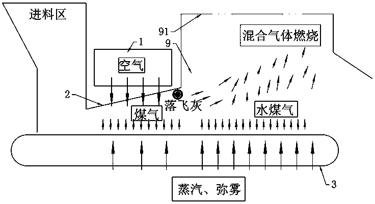
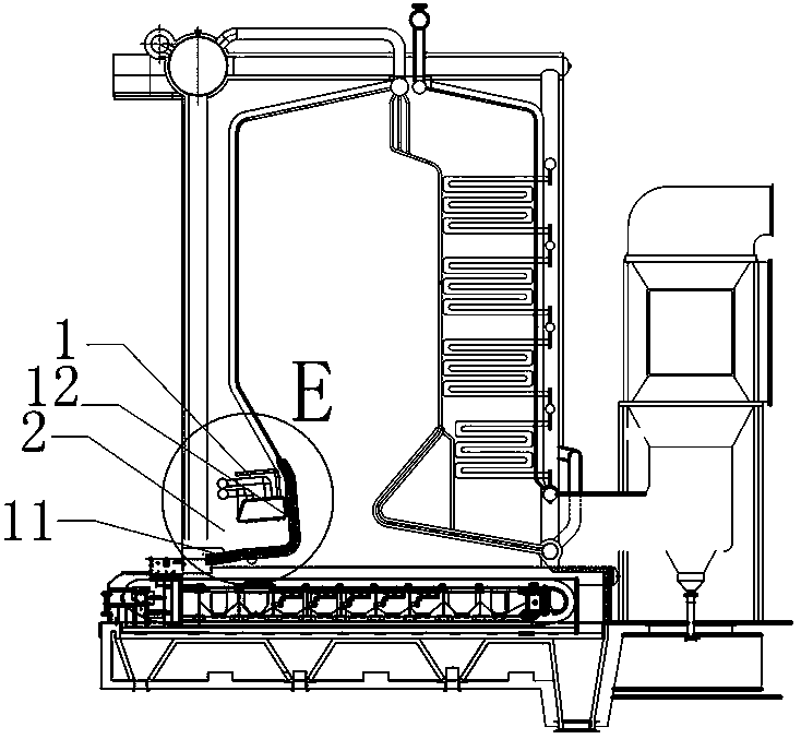
[0042] Such as figure 1 , figure 2 , image 3 and Figure 4 Commonly shown, an energy-saving and environment-friendly chain furnace, including a gasification device 1, the gasification device 1 is arranged on the upper part of the grate 3, and the gasification device 1 blows combustion-supporting air to the grate 3 from top to bottom.
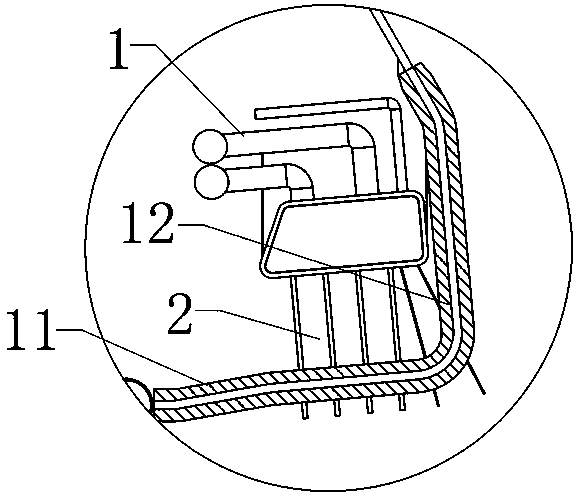
[0043] The gasification device 1 is arranged at the front arch 2, and the front arch 2 is provided with an open chamber for accommodating the gasification device 1. The open chamber for placing the gasification device 1 includes a bottom wall 11 and a side wall 12. The bottom wall 11 It is arranged horizontally, and the side wall 12 is arranged vertically.
[0044] The gasification device 1 has an air inlet and an air outlet, the air inlet of the gasification device 1 is connected with the combustion-supporting fan, and the combustion-supporting fan is arranged outside the chain furnace, and the air inlet of the gasification device 1 can al...
Embodiment 2
[0057] Depend on Figure 8 and Figure 9 As shown together, a kind of energy-saving and environment-friendly chain furnace in the present embodiment has basically the same structure as that in Embodiment 1, and its difference is:
[0058] A plurality of first holes 711 , a plurality of second holes 712 and a plurality of third holes 713 are arranged in rows and evenly distributed on the side wall of the casing 71 . The first hole 711, the second hole 712 and the third hole 713 are all provided with two rows. on the side walls. The bottom of the tail end of the housing 71 is also provided with a long hole 714 for unloading.
Embodiment 3
[0060] Depend on Figure 10 , Figure 11 and Figure 12 As shown together, a kind of energy-saving and environment-friendly chain furnace in the present embodiment has basically the same structure as that in Embodiment 1, and its difference is:
[0061] The fly ash conveying auger 7 includes a housing 71 and a screw shaft 72 rotatably arranged in the housing 71 . The casing 71 is arranged in an arc shape and is semicircular. The screw shaft 72 includes a plurality of shafts 721 connected in sequence, and two adjacent shafts 721 are connected by a universal joint 722 . The fly ash conveying auger 7 of this structure has a compact structure and can adapt to the arrangement of different spatial structures. A first hole 711 , a second hole 712 and a third hole 713 are sequentially provided on the housing 71 from bottom to top. There are multiple first holes 711 , second holes 712 and third holes 713 , and the diameters of the holes increase sequentially. The plurality of firs...
PUM
 Abstract
Description
Claims
Application Information
 - R&D
- Intellectual Property
- Life Sciences
- Materials
- Tech Scout
- Unparalleled Data Quality
- Higher Quality Content
- 60% Fewer Hallucinations
Browse by: Latest US Patents, China's latest patents, Technical Efficacy Thesaurus, Application Domain, Technology Topic, Popular Technical Reports.
© 2025 PatSnap. All rights reserved.Legal|Privacy policy|Modern Slavery Act Transparency Statement|Sitemap|About US| Contact US: help@patsnap.com


