
Coder

A technology of encoders and code channels, applied in the field of encoders, can solve the problems of poor phase consistency of UVW signals, many encoder parts, and not particularly compact structural design, etc.

Pending Publication Date: 2018-11-02
SHANGHAI LEIZHI MOTOR
View PDF0 Cites 7 Cited by
  • Summary
  • Abstract
  • Description
  • Claims
  • Application Information

AI Technical Summary

Problems solved by technology

[0011] Because the principle of the UVW signal generated by the magnetic ring through the hall component is different from that of the reading head signal, the phase consistency between the UVW signal and the ABZ signal is poor. equipment) cannot be used; moreover, this type of encoder has many parts, the process of installation is more complicated, and the structural design is not particularly compact, and there will be some restrictions on some occasions with strict requirements on the size of the motor.

Method used


Image

  • Coder
  • Coder
  • Coder

Examples


Embodiment Construction

[0030] In order to make the technical means, creative features, goals and effects achieved by the present invention easy to understand, the present invention will be further described below in conjunction with specific illustrations.

[0031] This example innovates and improves the existing encoder, using reflective photoelectric devices combined with reflective code discs to form a new encoder component module, and effectively achieve stable and accurate output U\V\W and other signals.

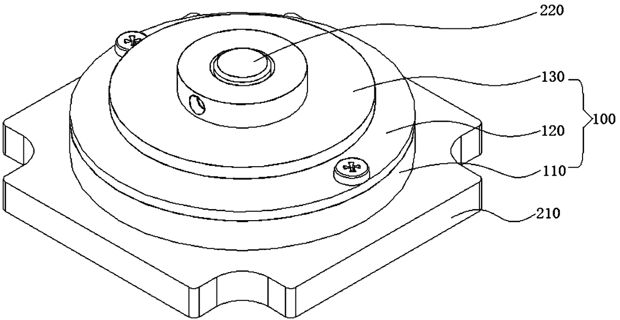
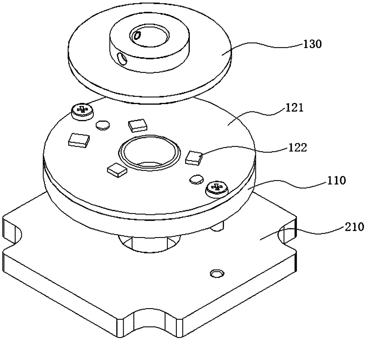
[0032] see figure 1 with figure 2 , which shows an example of the composition structure of the encoder given in this example.

[0033] It can be seen from the figure that the encoder 100 is mainly composed of an encoder bracket 110 , a PCB assembly 120 and a reflective code wheel 130 .

[0034] Wherein, the encoder bracket 110 constitutes the supporting structure of the entire encoder, and is used to carry other components. The encoder bracket 110 adopts a plastic molded part and incorpor...


PUM


Abstract

The invention discloses a coder, and the coder comprises a coder support, a PCB assembly, and a reflection-type code disc. An inner side of the PCB assembly is provided with a plurality of reflection-type photoelectric devices, and the PCB assembly is installed in the coder support in an integrated manner. The reflection-type code disc is provided with a plurality of code tracks on an inner side surface, and is arranged to be opposite to the PCB assembly. Moreover, the plurality of code tracks on the reflection-type code disc cooperate with the plurality of reflection-type photoelectric devices on the PCB assembly. According to the invention, the plurality of reflection-type photoelectric devices are employed for cooperating with the reflection-type code disc to form a new coder element module, thereby enabling the coder to stably and precisely output U\V\W signals, and to be higher in cost performance.

Description

technical field [0001] The invention relates to an encoder. Background technique [0002] With the development of science and technology and industrial automation, automatic control technology has been applied more and more in various fields. The servo system with the servo motor as the control object is gradually applied to all aspects of industrial production, scientific research and national defense. [0003] With the rapid development of software and hardware, various equipment (such as industrial robots, CNC machine tools and aerospace equipment, etc.) have higher and higher requirements for servo systems, such as: short response time, high stability of rotational speed and torque, and positioning accuracy High, and these put forward high requirements on the control method of the motor. [0004] At present, the relatively mature control method used in servo drive is vector control; to achieve the purpose of precise vector control, it is necessary to have precise encod...

Claims


Application Information

Patent Timeline
IPC IPC(8): G01D5/34
CPCG01D5/34
Inventor 荆红民朱凯张晨徐军
Owner SHANGHAI LEIZHI MOTOR
Learn More