Digital valve flow control system and optimal control method thereof

A valve flow, control system technology, applied in the direction of flow control, control/regulation system, flow control using electrical devices, etc., can solve problems such as inability to achieve valve opening positioning, difficult flow accurate control, and difficult opening adjustment of solenoid valves. , to achieve good stable performance and energy saving effect, good accuracy, good flow stability and interference resistance.

Inactive Publication Date: 2018-11-02
ANHUI UNIVERSITY OF TECHNOLOGY AND SCIENCE
View PDF14 Cites 2 Cited by
  • Summary
  • Abstract
  • Description
  • Claims
  • Application Information

AI Technical Summary

Problems solved by technology

Among them, solenoid valves and electric valves are the main actuators for flow regulation. Since it is difficult to adjust the opening of solenoid valves, electric valves have become the preferred actuators for flow control. However, in the existing electric valve applications, the valve The opening change process is not a linear process
The existing electric valve can only realize the adjustment of the valve opening, but cannot realize the positioning of the valve opening, so it is also difficult to realize the accurate control of the flow rate, especially the accurate estimation of the flow rate

Method used


Image

  • Digital valve flow control system and optimal control method thereof
  • Digital valve flow control system and optimal control method thereof
  • Digital valve flow control system and optimal control method thereof

Examples


Embodiment Construction

[0063] Through the description of the embodiments below, the specific implementation of the present invention includes the shape, structure, mutual position and connection relationship between the various parts, the function and working principle of each part, the manufacturing process and the operation and use method of the various components involved. etc., to make further detailed descriptions to help those skilled in the art have a more complete, accurate and in-depth understanding of the inventive concepts and technical solutions of the present invention.

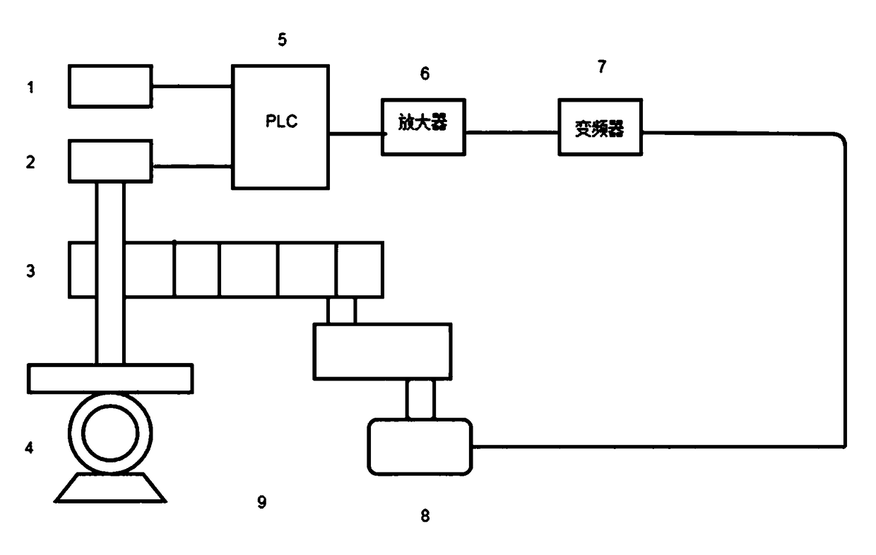
[0064] A digital valve flow control system, including a signal input device 1 for inputting a predetermined value, a V-shaped ball valve 4, a three-phase asynchronous motor 8 for controlling the valve opening of the V-shaped ball valve, a valve position feedback device 2, and a device for adjusting the three-phase asynchronous motor 8 Frequency converter 7, amplifier 6 and PLC 5 for rotation speed and direction of rotat...


PUM


Abstract

The invention discloses a digital valve flow control system and an optimal control method thereof. The system comprises a signal input device for inputting a preset value, a v-shaped ball valve, a three-phase asynchronous motor for controlling the opening degree of the v-shaped ball valve, a valve position feedback device, a frequency converter for adjusting the rotation number and the rotation direction of the three-phase asynchronous motor, an amplifier, and a PLC. The three-phase asynchronous motor is electrically connected with the frequency converter, and the frequency converter is electrically connected with the amplifier, and the valve position feedback device, the amplifier and the signal input device are all electrically connected with the PLC. The optimal control method comprisesthe steps that a transfer function of the system is established, and a state equation of the control system is worked out by the transfer function, and an optimal solution is performed on the state equation to obtain an optimal control system. The invention is advantageous in that flow stability and interference resistance are good; the intelligent control is adopted to enable the accurate valveflow control device to have relatively good stability and energy-saving effect.

Description

technical field [0001] The invention relates to the technical field of valve control, in particular to a digital valve flow control system and an optimal control method thereof. Background technique [0002] With the development of technology, the application of valves in people's lives is becoming more and more frequent, and the requirements for valve flow control are getting higher and higher, and more and more requirements are required for precision and simplification. Among them, solenoid valves and electric valves are the main actuators for flow regulation. Since it is difficult to adjust the opening of solenoid valves, electric valves have become the preferred actuators for flow control. However, in the existing electric valve applications, the valve The opening change process is not a linear process. The existing electric valve can only realize the adjustment of the valve opening, but not the positioning of the valve opening, so it is also difficult to realize the ac...

Claims


Application Information

Patent Timeline
Patent Type & Authority Applications(China)
IPC IPC(8): G05D7/06F16K31/04
CPCF16K31/04G05D7/0635
Inventor 王幼民谢鹏飞蒋秦帅随和许小娟李阿康
Owner ANHUI UNIVERSITY OF TECHNOLOGY AND SCIENCE
Why Eureka
Try Eureka