
Low smoke halogen free cross-linked insulation flame-retardant polyvinyl chloride sheath power cable

A flame-retardant polyvinyl chloride and cross-linked polyethylene technology, which is used in insulated cables, power cables, and power cables with shielding/conducting layers, etc., can solve the problems of low fire visibility, safe evacuation of personnel and fire obstructions, etc. To achieve the effect of ensuring the flame retardant effect

Inactive Publication Date: 2018-11-02
安徽庆华电缆有限公司
View PDF0 Cites 0 Cited by
  • Summary
  • Abstract
  • Description
  • Claims
  • Application Information

AI Technical Summary

Problems solved by technology

[0002] The combustion of wires and cables is due to the flammable gas generated by external heating. To achieve the purpose of flame retardancy, the three elements that cause combustion must be suppressed, namely: combustible gas, heat and oxygen. Therefore, the general method used for flame retardant wires and cables is Adding halogen-containing halides and metal oxides to materials such as insulation, sheathing, and filling is an excellent method from the perspective of flame retardancy. However, since these materials contain halides, they will A large amount of smoke and hydrogen halide gas are released, so the visibility of the fire is low, which greatly hinders the safe evacuation and fire fighting of personnel, and people are more likely to be suffocated to death by toxic gases.

Method used

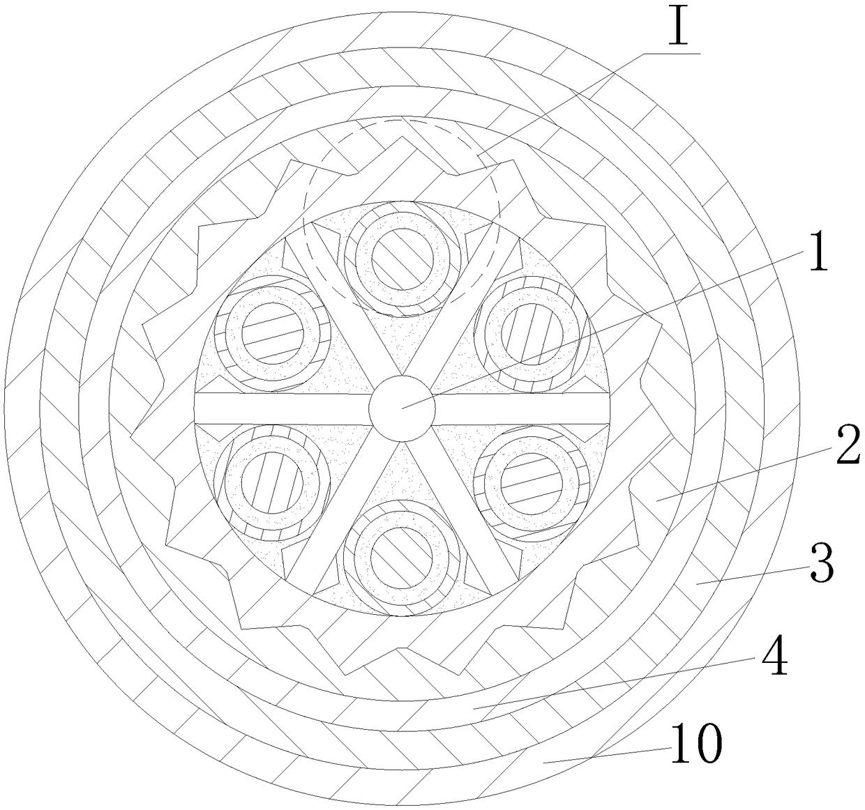
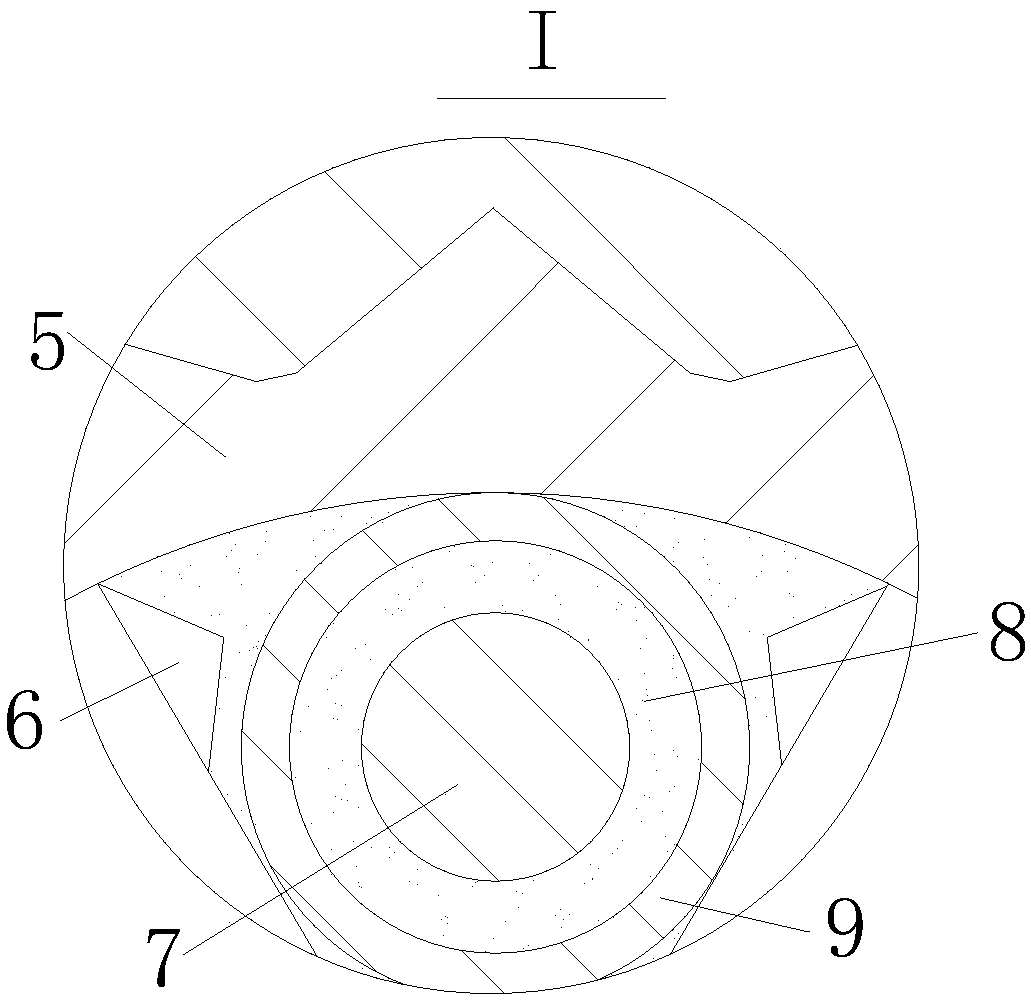

Image

  • Low smoke halogen free cross-linked insulation flame-retardant polyvinyl chloride sheath power cable
  • Low smoke halogen free cross-linked insulation flame-retardant polyvinyl chloride sheath power cable

Examples


Embodiment Construction

[0015] In order to make the technical means, creative features, goals and effects achieved by the present invention easy to understand, the present invention will be further elaborated below.

[0016] Such as figure 1 with figure 2 As shown, a low-smoke halogen-free cross-linked insulated flame-retardant polyvinyl chloride sheathed power cable includes several cable cores. The cable cores include annealed copper conductor 7 and low-smoke Halogen-free cross-linked polyethylene insulation layer 9, the stranding centers of the several cable cores are provided with isolation plates 1 with a hexagonal snowflake-shaped cross-section, and both sides of the ends of the isolation plates 1 are provided with The tooth tip 6 to prevent the cable core from sliding, the cross section of the tooth tip 6 is triangular, the outer part of the isolation plate 1 is extruded with a ratchet-shaped flame retardant layer 5, the flame retardant The outside of layer 5 is extruded with a signal shiel...


PUM


Abstract

The invention relates to the technical field of cables, in particular to a low smoke halogen free cross-linked insulation flame-retardant polyvinyl chloride sheath power cable. The low smoke halogen free cross-linked insulation flame-retardant polyvinyl chloride sheath power cable comprises a plurality of cable cores, wherein each cable core comprises an annealing copper conductor and a low smokehalogen free cross-linked insulation flame-retardant polyvinyl chloride insulation layer, the low smoke halogen free cross-linked insulation flame-retardant polyvinyl chloride insulation layer is arranged outside the annealing copper conductor in an extruded manner, an isolation plate is arranged at a central position of the plurality of cable cores, tooth tips are arranged at two sides of an endpart of the isolation plate, a flame-retardant layer is arranged outside the isolation plate in an extruded manner, a signal shielding layer is arranged outside the flame-retardant layer in an extruded manner, a metal armoring layer wraps the signal shielding layer, a buffer layer wraps the metal armoring layer, and a polyvinyl chloride sheath is arranged outside the buffer layer in an extruded manner. The cable cores are isolated by the isolation plate with snowflake-shaped cross section, and the cable cores are prevented from being twisted to affect a transmission effect; and the internal relative stability of the cable is guaranteed by the flame-retardant layer with ratchet-shaped cross section, and meanwhile, the flame-retardant effect can be guaranteed.

Description

technical field [0001] The invention relates to the technical field of cables, in particular to a low-smoke, halogen-free, cross-linked insulated, flame-retardant polyvinyl chloride sheathed power cable. Background technique [0002] The combustion of wires and cables is due to the flammable gas generated by external heating. To achieve the purpose of flame retardancy, the three elements that cause combustion must be suppressed, namely: combustible gas, heat and oxygen. Therefore, the general method used for flame retardant wires and cables is Adding halogen-containing halides and metal oxides to materials such as insulation, sheathing, and filling is an excellent method from the perspective of flame retardancy. However, since these materials contain halides, they will A large amount of smog and hydrogen halide gas are released, so the visibility during the fire is low, which greatly hinders the safe evacuation and fire fighting of personnel, and people are more likely to su...

Claims


Application Information

Patent Timeline
IPC IPC(8): H01B7/17H01B7/18H01B7/295H01B9/00H01B9/02
CPCH01B9/006H01B7/17H01B7/1815H01B7/295H01B9/021H01B9/027
Inventor 陶成刚
Owner 安徽庆华电缆有限公司
Learn More