Stator blade finish forging automatic machining method

A stator blade and processing method technology, applied in the field of automatic processing of precision forging stator blades, can solve the problems of complex process, low processing efficiency, low qualified rate of blade surface profile, etc. unhindered effect

Active Publication Date: 2018-11-06
AECC AVIATION POWER CO LTD
View PDF10 Cites 10 Cited by
  • Summary
  • Abstract
  • Description
  • Claims
  • Application Information

AI Technical Summary

Problems solved by technology

[0003] The traditional processing method needs to change the machine tool many times and change the process reference plane to

Method used


Image

  • Stator blade finish forging automatic machining method
  • Stator blade finish forging automatic machining method
  • Stator blade finish forging automatic machining method

Examples


Embodiment Construction

[0040] The present invention is described in further detail below in conjunction with accompanying drawing:

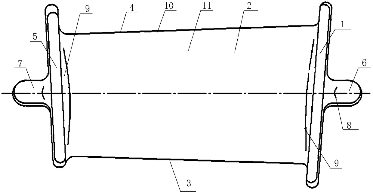
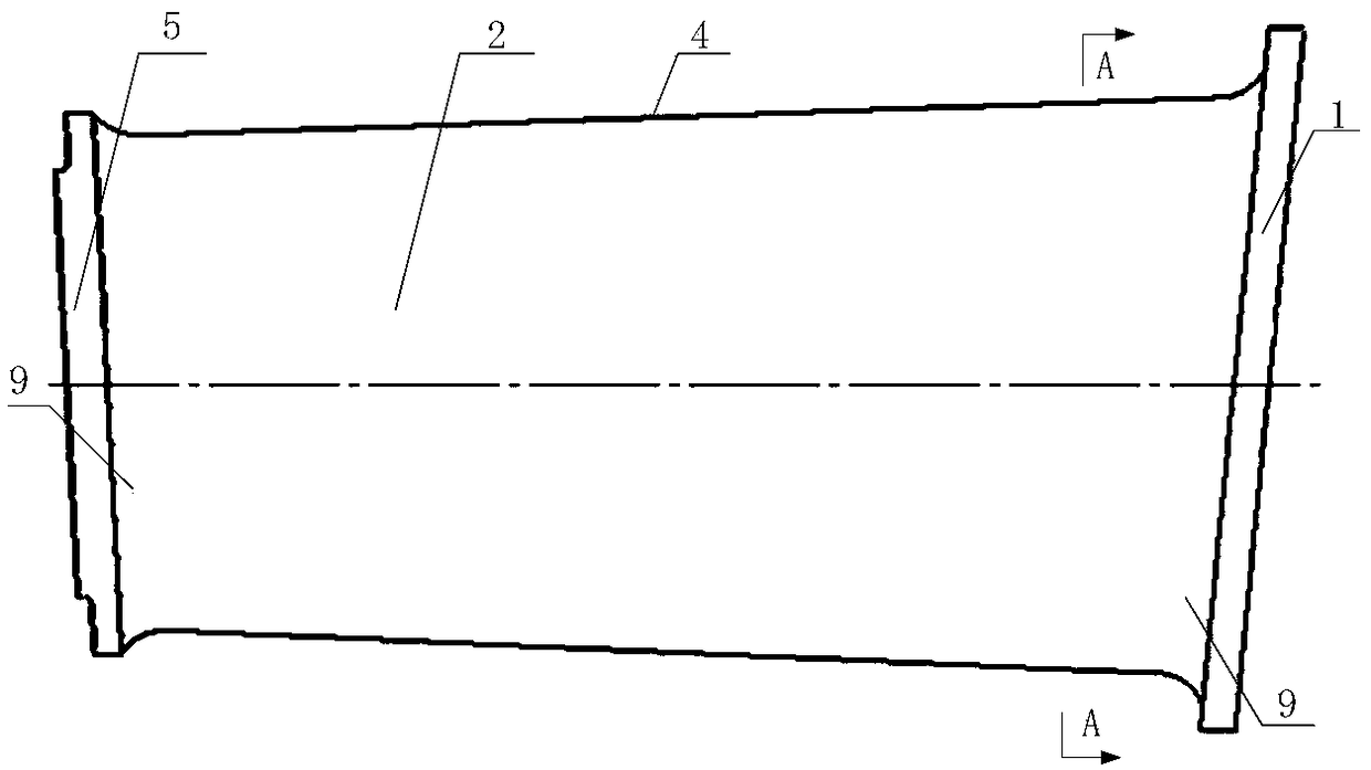
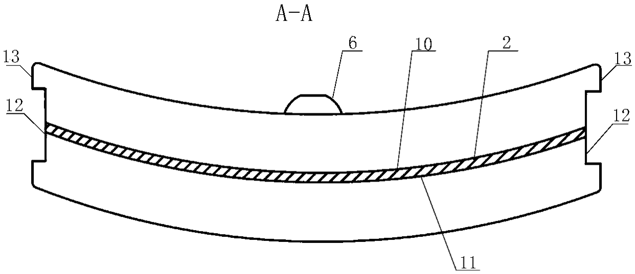
[0041] see figure 1 and image 3 , the engine stator blank blade of the present invention is a precision forging, and the blank blade includes an upper edge plate 1, a blade body 2, an exhaust edge 3, an air intake edge 4, a lower edge plate 5, a process upper boss 6, and a process lower boss 7 , transfer arc surface 9; the concave surface of the blade body 2 is the blade basin 10, and the convex surface of the blade body 2 is the blade back 11; one side of the blade body 2 is the exhaust edge 3, and the other side is the air intake edge 4; One end of 2 is the upper edge plate 1, and the other end is the lower edge plate 5; the outer surface of the upper edge plate 1 is fixedly connected with the upper boss 6 of the process, and the outer side of the lower edge plate 5 is fixedly connected with the lower boss 7 of the process. The fixed surface of the lower edge plat...


PUM


Abstract

The invention discloses a stator blade finish forging automatic machining method. The method adopts a self-adaption machining technology, and blade deviation, torsion, profile surface tolerance and machining consistency are ensured. The method is simple in machining procedure, computer control and management are adopted, controlled devices completely automatically finish the sequential operation,the degree of automatic operation is improved, multiple devices, multiple passes of procedures, repeated clamping and repeated standard conversion for original stator blade machining are reduced intotwo passes of procedures of machining, two times of clamping and one time of standard conversion on one kind of equipment, labor is saved, the production period of parts is shortened, and the production efficiency is improved.

Description

【Technical field】 [0001] The invention belongs to the technical field of aeroengine blade processing, and in particular relates to an automatic processing method for precision forging stator blades. 【Background technique】 [0002] At this stage, the processing technology of the stator blade mainly adopts die forging blanks, and the main process of the process is: (1) the milling basin, the long side of the back side edge plate and the process convex table; (2) the milling basin, the length of the back side edge plate Side and process boss surface; (3) milling row, end of air intake side edge plate; (4) milling edge plate bottom surface, process boss end face; (5) milling, exhaust side lower edge plate end face; ( 6) CNC milling basin, back side blade body, lower edge plate surface and upper and lower edge plate transfer R; (7) milling basin, back side edge plate long side; (8) milling, exhaust side edge Plate end; (9) Grinding inlet and exhaust side lower edge plate end; (1...

Claims


Application Information

Patent Timeline
IPC IPC(8): B23P15/02B23C3/18
CPCB23C3/18B23P15/02
Inventor 蓝仁浩李飞刘金凤张义德蒲海龙郭海张静怡
Owner AECC AVIATION POWER CO LTD
Why Eureka
Try Eureka