Photovoltaic glass curtain wall polishing device
A photovoltaic glass and polishing device technology, which is applied to grinding drive devices, grinding/polishing equipment, grinding machines, etc., can solve the problems of complex structure and low polishing efficiency of polishing devices, and achieve simple structure, high polishing efficiency, and solution structure. complex effects
- Summary
- Abstract
- Description
- Claims
- Application Information
AI Technical Summary
Problems solved by technology
Method used
Image

Examples
Embodiment 1
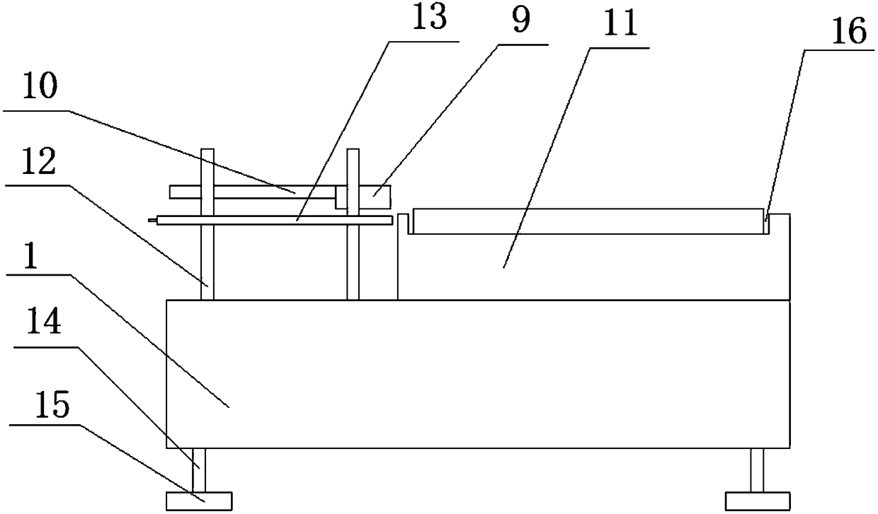
[0028] A photovoltaic glass curtain wall polishing device, comprising a machine base, a placement platform is arranged on the right side of the machine base, a guide column is arranged on the left side of the machine base, a mobile platform is set on the guide column, a polishing mechanism is installed on the mobile platform, and the polishing mechanism It includes a chute arranged along the width direction of the mobile platform, a slider is arranged in the chute, a first connecting rod is hinged on the slider, a polishing plate is hinged on the other end of the first connecting rod, and the moving platform is located in front of the chute and also connected to There is a connecting seat, a driving rod is hinged on the connecting seat, and the other end of the driving rod is hinged with the middle part of the first connecting rod. Through this setting, put the photovoltaic glass curtain wall to be polished on the placement table, move the mobile table down along the guide colu...
Embodiment 2
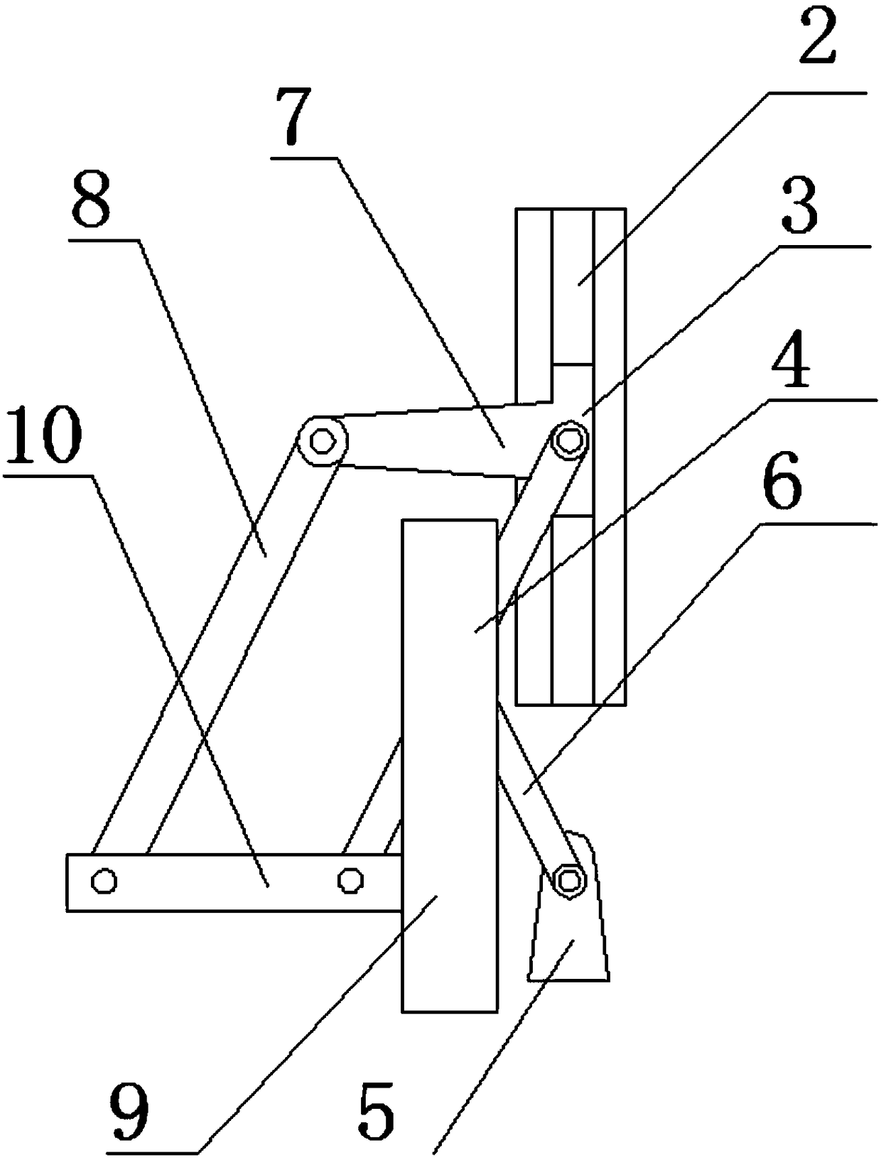
[0030] On the basis of Embodiment 1, a connecting plate is arranged on the slider along the left side of the slider, the end of the connecting plate is hinged with a second connecting rod, the left end of the polishing plate is connected with a connecting handle, and the other part of the second connecting rod One end is hinged with the left end of the connecting handle, and the other end of the first connecting rod is hinged with the right end of the connecting handle. Through this setting, the driving rod swings to the right, driving the first connecting rod to swing counterclockwise. During the swinging process of the first connecting rod, it drives the slider to slide upward, and the slider drives the connecting plate to move upward. The lower end of the first connecting rod and the second The lower ends of the two connecting rods swing to the right at the same time and drive the connecting handle to move to the right, thereby driving the polishing plate to move to the righ...
Embodiment 3
[0032] On the basis of the above embodiments, a drive motor for driving the drive rod to rotate is also mounted on the connecting seat. Through this setting, the driving motor drives the driving rod to rotate, so that the driving rod swings more stably and has a higher degree of automation.
PUM
 Abstract
Description
Claims
Application Information
 - Generate Ideas
- Intellectual Property
- Life Sciences
- Materials
- Tech Scout
- Unparalleled Data Quality
- Higher Quality Content
- 60% Fewer Hallucinations
Browse by: Latest US Patents, China's latest patents, Technical Efficacy Thesaurus, Application Domain, Technology Topic, Popular Technical Reports.
© 2025 PatSnap. All rights reserved.Legal|Privacy policy|Modern Slavery Act Transparency Statement|Sitemap|About US| Contact US: help@patsnap.com