A method for preparing composite material pipe by using inner expansion method forming mold

A composite material tube and forming die technology, which is applied in the field of aviation composite material forming, can solve the problems of difficult forming of composite material tubes, and achieve the effects of uniform wall thickness, convenient operation, overcoming difficult sealing and easy air leakage.

Active Publication Date: 2020-01-21
GUANGLIAN AVIATION IND CO LTD
View PDF6 Cites 0 Cited by
  • Summary
  • Abstract
  • Description
  • Claims
  • Application Information

AI Technical Summary

Problems solved by technology

[0004] The purpose of the present invention is to provide a method for preparing composite material pipes by using the internal expansion molding die, and the present invention solves the problem of difficult forming of composite material pipes that require high precision on the outer surface

Method used


Image

  • A method for preparing composite material pipe by using inner expansion method forming mold
  • A method for preparing composite material pipe by using inner expansion method forming mold
  • A method for preparing composite material pipe by using inner expansion method forming mold

Examples


specific Embodiment approach 1

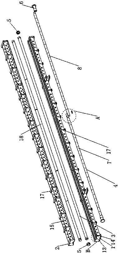
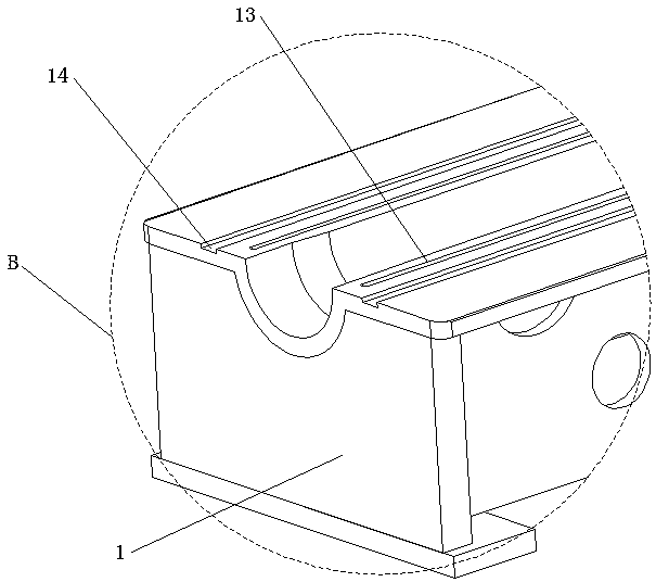
[0038] Specific implementation mode one: as Figure 1-Figure 5 As shown, this embodiment discloses a method for preparing a composite material pipe using an internal expansion molding die, and the method includes the following steps:

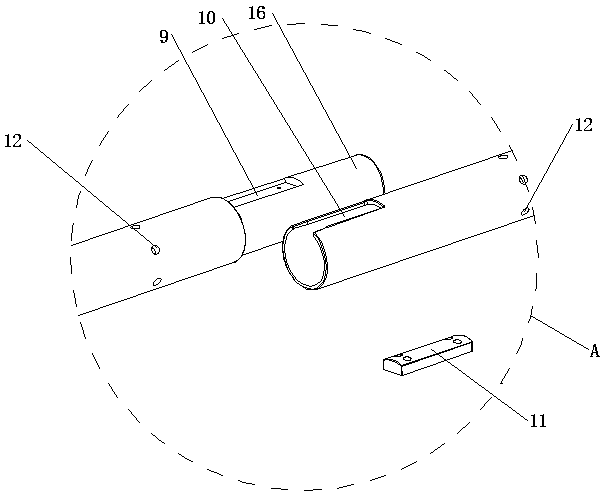
[0039] Step 1: the connection of metal mandrel 1 7 and metal mandrel 2 8; metal mandrel 1 7 and metal mandrel 2 8 are metal round tubes, and the outer pipe diameters are the same, and the cone set at one end of metal mandrel 7 is Type connection boss 16 is matched with the taper hole that metal mandrel two 8 one ends are provided with, and the retaining groove one 9 that is provided with on the tapered connection boss 16 outer wall of metal mandrel one 7 is provided with metal mandrel two 8 places The retaining groove 2 10 that is provided with at one end is oppositely arranged and embedded in the retaining key 11 (to prevent the metal mandrel 1 7 and the metal mandrel 2 8 from rotating mutually), and the metal mandrel 1 7 other end is provided ...

specific Embodiment approach 2

[0050] Embodiment 2: This embodiment is a further description of Embodiment 1. In step 3 of this embodiment, when the ambient temperature and humidity conditions meet the requirements, the temperature is 18-22° C. and the humidity is less than 25-30%. The purpose is to avoid ply defects.

specific Embodiment approach 3

[0051] Specific embodiment three: This embodiment is a further description of specific embodiment one or two. In step six of this embodiment, the preparation method of the vacuum bag is: paste a circle of putty strips on the bag-making area, and then paste the vacuum film , and then connect the air source to the vacuum nozzle connected to the vacuum membrane for vacuuming.

[0052] The retaining key 11 used in the present invention is a cylindrical connection key.

[0053] In the present invention, both the lower mold body 1 and the upper mold body 2 are provided with hoisting rings 19 .


PUM

PropertyMeasurementUnit
lengthaaaaaaaaaa

Abstract

The invention belongs to the field of aeronautical composite materials and discloses a method for preparing composite tubes by an internal-expanding forming mould. The method includes: step one, connection of a first metal mandrel and a second metal mandrel; step two, composition of a silicon rubber mandrel component; step three, composite material lamination; step four, placement of a semi-finished product in a cavity of an upper mould body and a lower mould body and pre-compacting; step five, combination of fixation of the upper mould body and the lower mould body; step six, vacuumizing of the upper mould body and the lower mould body; step seven, solidifying and demoulding. By forming according to the method, the composite tubes longer than 9m can be manufactured, and the method is notreported so far due to high forming difficulty. The method belongs to composite structure integral forming techniques.

Description

technical field [0001] The invention belongs to the field of aviation composite material forming, and in particular relates to a method for preparing a composite material pipe by using an internal expansion forming mold. Background technique [0002] Carbon fiber composite materials are more and more widely used in aircraft due to their specific strength, large specific modulus, light weight, corrosion resistance, fatigue resistance, and strong designability. The application parts of composite materials on aircraft have gradually developed from non-load-bearing parts and secondary load-bearing parts to main load-bearing parts, and are developing in the direction of large-scale, complex and integrated. The amount of advanced composite materials has become an important indicator of the advanced nature of aircraft. [0003] Composite material parts are usually formed by vacuum bag method, and composite material tube is formed. Due to the high requirement of outer surface rough...

Claims


Application Information

Patent Timeline
Patent Type & Authority Patents(China)
IPC IPC(8): B29C70/34
CPCB29C70/342
Inventor 李娜杨守吉郑霏张明洋
Owner GUANGLIAN AVIATION IND CO LTD
Why Eureka
Try Eureka