Glass melting furnace and glass melting method

A technology of glass melting furnace and glass melting furnace, which is applied in the direction of glass manufacturing equipment, glass furnace equipment, manufacturing tools, etc. It can solve the problems of refractory material erosion or condensate dripping, volatile glass, and obvious problems, so as to reduce maintenance Effects of cost, extended service life, and strong structural flexibility

Active Publication Date: 2018-11-06
SHANGHAI YAOHUA PILKINGTON GLASS GROUP +1
View PDF9 Cites 2 Cited by
  • Summary
  • Abstract
  • Description
  • Claims
  • Application Information

AI Technical Summary

Problems solved by technology

[0004] However, the current problem in the field of glass melting is that the glass batch material will volatilize certain components during the process of melting into glass liquid or during the clarification process, such as sodium oxide, sulfur dioxide, boron oxide, lead compounds, water vapor, etc. , especially high borosilicate glass, low melting point glass and leaded glass, etc., the volatilization phenomenon is more significant, and the volatilization amount of some components may even exceed 10% of its content in the glass
[0008] However, none of the above solutions can solve the problem that the volatilized components of the volatile glass will condense on the refractory structure of the furnace during the melting process, causing erosion to the refractory material or the condensation will drop into the glass to form defects.

Method used


Image

  • Glass melting furnace and glass melting method
  • Glass melting furnace and glass melting method
  • Glass melting furnace and glass melting method

Examples


Embodiment 1

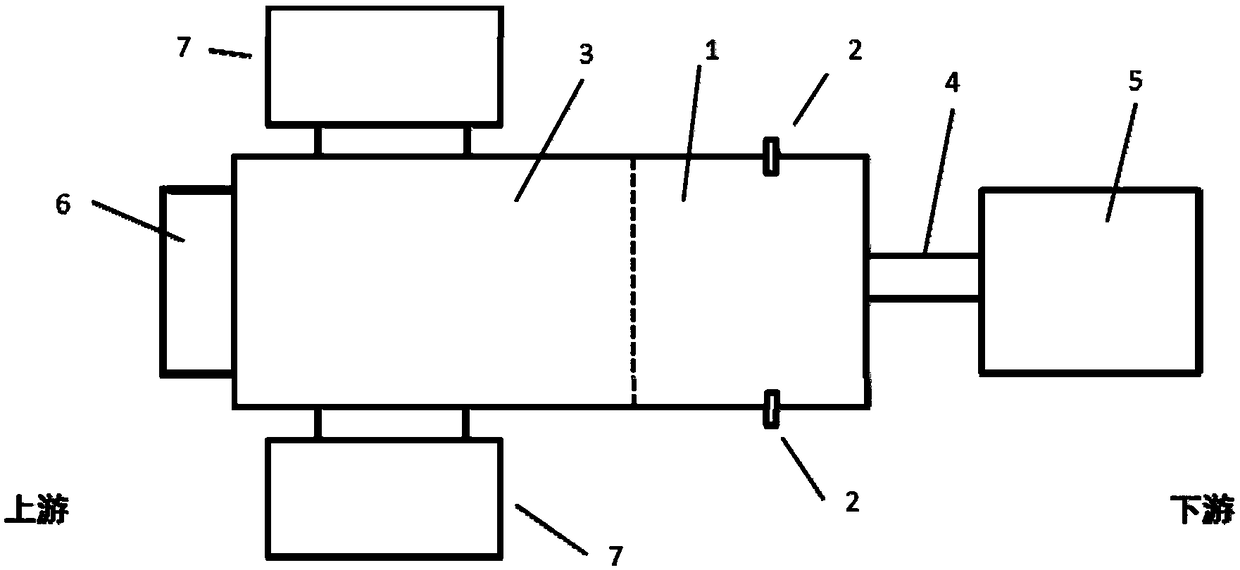
[0062] The schematic diagram of the top view structure of the glass melting furnace used in this embodiment is as follows figure 1 As shown, the glass melting furnace includes: a clarifying part 1 , a spray gun 2 , a melting part 3 , a flow hole 4 , a cooling part 5 , a feed port 6 and a heat accumulator 7 . The melting part 3, the clarification part 1, the liquid flow hole 4 and the cooling part 5 are connected in sequence, the clarification part 1 and the melting part 3 are integrated into one space, and the side where the clarification part 1 is connected with the liquid flow hole 4 is provided with a rear gable to clarify There are breast walls on both sides of part 1.

[0063] Two spray guns 2 are symmetrically arranged on both sides of the parapet wall of the clarification part 1. The distance of the spray gun 2 above the glass liquid is 0.6m. All are air spray guns, and the nozzle materials are all refractory materials. The nozzles of the two spray guns 2 are all alig...

Embodiment 2

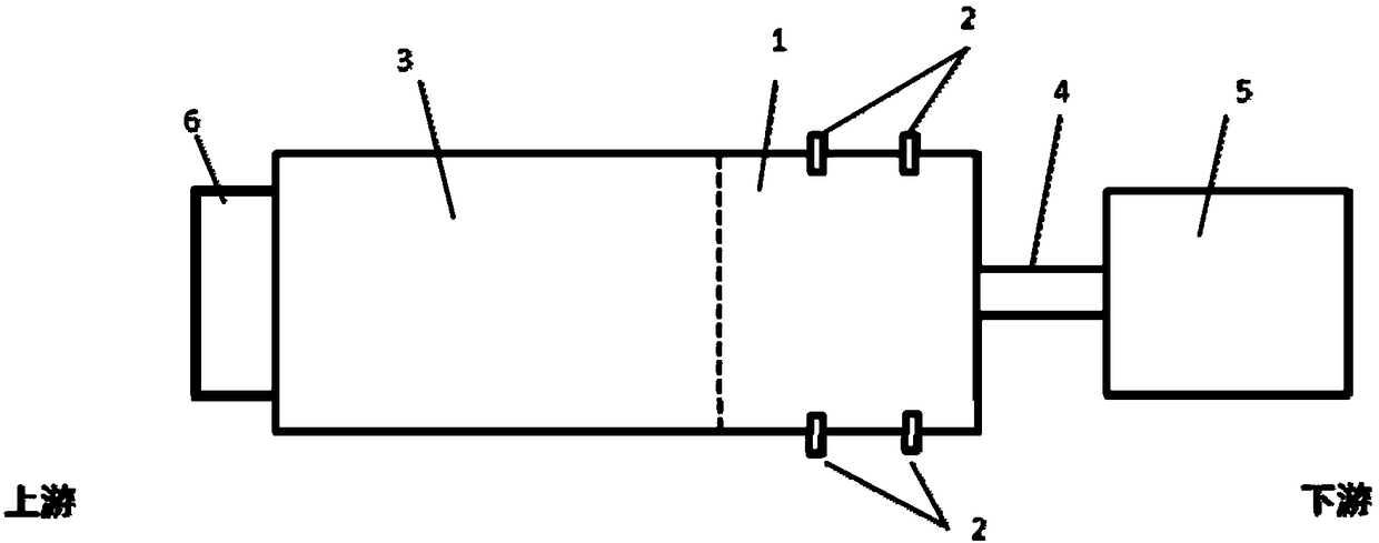
[0070] The schematic diagram of the top view structure of the glass melting furnace used in this embodiment is as follows figure 2 As shown, the glass melting furnace includes: a clarifying part 1 , a spray gun 2 , a melting part 3 , a flow hole 4 , a cooling part 5 and a feed port 6 . The melting part 3, the clarification part 1, the liquid flow hole 4 and the cooling part 5 are connected in sequence, the clarification part 1 and the melting part 3 are integrated into one space, and the side where the clarification part 1 is connected with the liquid flow hole 4 is provided with a rear gable to clarify There are breast walls on both sides of part 1.

[0071] Four spray guns 2 are symmetrically arranged in pairs on both parapet walls of the clarification unit 1. The distance of the spray guns 2 above the molten glass is 1m, and the installation position of the spray gun 2 nearest to the gable wall of the clarification unit 1 is at the level of the gable wall of the clarificat...

Embodiment 3

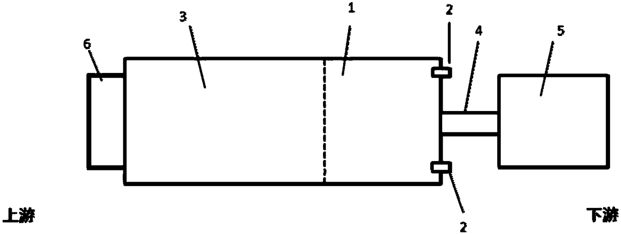
[0078] The schematic diagram of the top view structure of the glass melting furnace used in this embodiment is as follows image 3 As shown, the glass melting furnace includes: a clarifying part 1 , a spray gun 2 , a melting part 3 , a flow hole 4 , a cooling part 5 and a feed port 6 . The melting part 3, the clarification part 1, the liquid flow hole 4 and the cooling part 5 are connected in sequence, the clarification part 1 and the melting part 3 are integrated into one space, and the side where the clarification part 1 is connected with the liquid flow hole 4 is provided with a rear gable to clarify There are breast walls on both sides of part 1.

[0079] Two spray guns 2 are arranged in pairs on the back gable wall of the clarification part 1. The distance of the spray guns 2 above the molten glass is 1m. The two spray guns 2 are all oxygen spray guns, and the nozzle materials are all refractory materials. The spray nozzles of the two spray guns 2 are all retracted in th...


PUM


Abstract

The invention provides a glass melting furnace and a glass melting method. A clarification part of the glass melting furnace contains spray guns, and the spray guns are fixed in the clarification part. The glass melting method comprises the steps of adding raw materials for preparing glass into the glass melting furnace, performing glass melting, opening the spray guns of the clarification part ofthe glass melting furnace in the glass melting process, and obtaining a glass melting solution with the viscosity meeting molding requirements. According to the provided glass melting furnace, by arranging the spray guns in the clarification part, volatile components generated in the glass melting process are blown out of the melting furnace and can be diluted, the concentration of the volatile components in the melting furnace is decreased, the volatile components cannot be condensed on a refractory material of the melting furnace, the service life of the glass melting furnace is prolonged,and the maintenance cost is reduced. At the same time, defects, in the glass, caused by falling due to erosion of the surface of the refractory material cannot occur, and the quality of the glass melting solution is ensured.

Description

technical field [0001] The invention belongs to the technical field of glass production, and in particular relates to a glass melting furnace and a method for melting glass. Background technique [0002] In the glass production process, the process of heating batch materials to form glass is called glass melting process. Glass melting is an important stage in the glass production process. The quality and speed of melting determine the quality and output of products. [0003] The melting of glass needs to be carried out in a glass melting furnace. The glass melting furnace is a kind of melting device that the glass manufacturing industry must have. The inner high temperature melts, clarifies and forms molten glass that meets the molding requirements. Glassmaking is 5,000 years old, and the method of making glass, fueled by firewood, by melting glass batches in clay pots has continued for a long time. In 1867, the German Siemens brothers built a continuous coal-fired pool k...

Claims


Application Information

Patent Timeline
Patent Type & Authority Applications(China)
IPC IPC(8): C03B5/225C03B5/235
CPCC03B5/225C03B5/235
Inventor 李志进刘明清田力董自强马惠平徐峥傅星军符建波董俊傅君玮
Owner SHANGHAI YAOHUA PILKINGTON GLASS GROUP
Why Eureka
Try Eureka