Pulse-impact rock breaking drill bit

A pulsating impact, drill bit technology

A pulsating impact, drill bit technology

CN108756733AActive Publication Date: 2018-11-06SOUTHWEST PETROLEUM UNIV

Image

  • Pulse-impact rock breaking drill bit
  • Pulse-impact rock breaking drill bit
  • Pulse-impact rock breaking drill bit

Examples


Embodiment Construction

[0020] The present invention will be further described below in conjunction with the accompanying drawings, but the protection scope of the present invention is not limited to the following description.

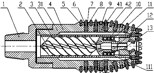
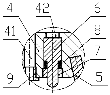
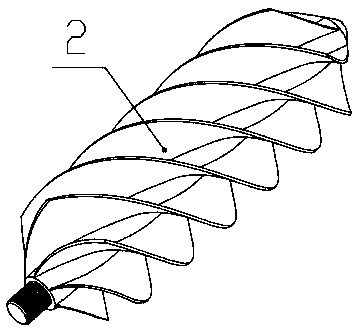
[0021] Such as figure 1 , figure 2 , image 3 As shown, a pulsating impact rock-breaking drill bit includes an upper joint 1, a drill bit base 4, a fixed cutting tooth 5, an impact cutting tooth 6, a nozzle 9, a moving valve ring 12 and a static valve ring 13, the upper end of the upper joint 1 and the upper Drill string screw connection, the lower end of the upper joint 1 is connected with the upper end of the drill base 4 with a screw, the lower part of the outer circle of the drill base 4 is set as a conical surface, and the lower part of the outer circle of the drill base 4 is provided with a water eye 41, and the water eye 41 is connected to the inside and outside of the drill base 4 cavity, the outlet end of the water eye 41 is set as a female thread, the outer circl...


PUM


Abstract

The invention discloses a pulse-impact rock breaking drill bit. The upper end of an upper joint is in threaded connection with an upper drill column, and the lower end of the upper joint is in threaded connection with the upper end of a drill bit base body. Fixed cutting teeth are mounted in an interference mode in blind holes which are regularly distributed in the surface of the lower portion ofthe drill bit base body. A nozzle and a water outlet in the lower portion of the outer circumference of the drill bit base body are fastened in a threaded mode, impact cutting teeth and a disc springare integrally mounted in a stepped hole of the drill bit base body, and a sealing cover and the outlet end of the stepped hole in the drill bit base body are fastened in a threaded mode. A spiral blade is arranged on the upper portion of a spiral rotor, and the spiral rotor, a rolling bearing, a bearing seat and a dynamic valve ring are integrally placed in an inner cavity of a bushing pipe. Thedrill bit can generate impact rock-breaking loads to rock strata while completing the conventional PDC drill bit rock breaking mechanism, a good rock breaking effect to hard stratum brittle rock is achieved, and the mechanical rotating speed is effectively increased.

Description

technical field [0001] The invention relates to drilling in hard formations in the petroleum and natural gas industry, in particular to a pulsating impact rock-breaking drill bit. Background technique [0002] In the oil and gas industry, drilling operations are risky, difficult, and highly economically rewarding. During the drilling process, increasing the ROP can effectively shorten the drilling cycle, reduce operating costs, and increase economic benefits. Therefore, how to effectively increase the ROP has always been an important technical problem in the field of oil drilling at home and abroad. In drilling operations, drilling in hard formations is the most difficult, because the hard formations are hard and have good wear resistance, which makes it difficult for the drill bit to cut hard formation rocks. At present, the most common applications at home and abroad are roller cone bits and PDC bits. Under the action of drill pressure and drill string rotation, the teeth...

Claims


Application Information

Patent Timeline
06 Nov 2018
Publication
CN108756733A
IPC
E21B4/16; E21B10/46; E21B10/56; E21B12/00
CPC
E21B4/16; E21B10/46; E21B10/56; E21B12/00
Inventors
杨火海; 杨兆中