
Steam generator for metal fast reactor

A steam generator and metal technology, which is applied in the field of nuclear power plant equipment, can solve the problems of inability to carry out the maintenance work of heat exchanger heat exchange tube blockage, affecting the natural circulation capacity of liquid metal, and increasing the flow resistance of liquid metal, so as to improve the natural Cycling capability, improving inherent safety, reducing the effect of abrasion

Inactive Publication Date: 2018-11-06
CHINA NUCLEAR POWER TECH RES INST CO LTD +3
View PDF4 Cites 1 Cited by
  • Summary
  • Abstract
  • Description
  • Claims
  • Application Information

AI Technical Summary

Problems solved by technology

[0002] The steam generators used in nuclear reactors generally use titanium tubes as the corrosion-resistant layer. Since the operating temperature of titanium tubes is below 425 degrees Celsius, this greatly limits the operating temperature range of this type of steam reactor and will not be suitable for metal blocks. In the stack field, titanium tubes are used as the corrosion-resistant layer, which increases the cost of heat exchanger manufacturing. The commonly used U-shaped heat transfer tubes need to be equipped with anti-vibration strips at the bends, and due to the high viscosity of liquid metal, it is easy to corrode heat transfer tubes. Heat pipe, if the liquid metal flows in the tube side, it will increase the flow resistance of the liquid metal, increase the requirements for the liquid metal delivery pump, and affect the natural circulation ability of the liquid metal, and the multi-layer casing structure is used in the steam generator , it will be difficult to carry out in-service inspection work, and due to the existence of multi-layer tube sheets, it will not be possible to carry out plugging maintenance work for heat exchange tubes of heat exchangers

Method used


Image

  • Steam generator for metal fast reactor
  • Steam generator for metal fast reactor
  • Steam generator for metal fast reactor

Examples


Embodiment Construction

[0023] The following descriptions of various embodiments refer to the accompanying drawings to illustrate specific embodiments in which the present invention can be implemented.

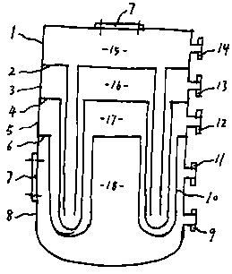
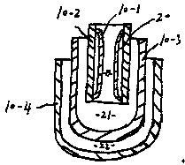
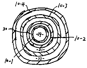
[0024] The following will combine Figure 1-3 Specifically, the steam generator includes a container body and a heat exchanger 10 arranged in the container body, and the container body is provided with a primary side outlet 9, a primary side inlet 11, and a secondary side outlet 13 from bottom to top. , the secondary side inlet 14, at least the shell side 18 and the first tube side are formed in the container main body.

[0025] The high-temperature medium enters the shell side 18 through the primary side inlet 11, and is exported from the primary side outlet 9 after being cooled;

[0026] The low-temperature medium enters the first tube through the secondary side inlet 14 and is led out from the secondary side outlet 13 after being heated.

[0027] Wherein, the heat exchanger 10 includes a first h...


PUM


Abstract

The invention provides a steam generator for metal fast reactor. The steam generator comprises a container body and a heat exchanger arranged in the container body. The container body is provided witha primary side outlet, a primary side inlet, a secondary side outlet and a secondary side inlet from bottom to top, and at least a shell pass and a first pipe pass are formed in the container body. Ahigh-temperature medium enters the shell pass through the primary side inlet, and is exported from the primary side outlet after cooling. A low-temperature medium enters the first pipe pass through the secondary side inlet, and is exported from the secondary side outlet after heating. According to the steam generator for the metal fast reactor, the mode that the high-temperature medium flows through the shell pass and the low-temperature medium flows through the pipe pass is used, the velocity of the shell pass as well as the abrasion degree of the pipe wall of a heat exchange pipe and the container wall are reduced, the circulation ability is improved, and the reliability and safety of the steam generator are improved.

Description

technical field [0001] The invention relates to the technical field of nuclear power plant equipment, in particular to a steam generator for metal fast reactors. Background technique [0002] The steam generators used in nuclear reactors generally use titanium tubes as the corrosion-resistant layer. Since the operating temperature of titanium tubes is below 425 degrees Celsius, this greatly limits the operating temperature range of this type of steam reactor and will not be suitable for metal blocks. In the stack field, titanium tubes are used as the corrosion-resistant layer, which increases the cost of heat exchanger manufacturing. The commonly used U-shaped heat transfer tubes need to be equipped with anti-vibration strips at the bends, and due to the high viscosity of liquid metal, it is easy to corrode heat transfer tubes. For heat pipes, if the liquid metal flows in the tube side, it will increase the flow resistance of the liquid metal, increase the requirements for t...

Claims


Application Information

Patent Timeline
Patent Type & Authority Applications(China)
IPC IPC(8): F22B1/06F28D7/08F28F19/00
CPCF22B1/063F28D7/08F28F19/00
Inventor 黎勋翟立宏路广遥唐叔建吴凤岐李其朋曹学冰王弟东魏超周建明刘强周国丰
Owner CHINA NUCLEAR POWER TECH RES INST CO LTD
Learn More