Optimum flat plate structure design method for improving transient vibration isolation performance

A technology for optimized design and transient vibration, applied in design optimization/simulation, calculation, special data processing applications, etc., can solve problems such as multi-parameter parallel optimization, and achieve the effect of improving transient vibration isolation performance and improving vibration isolation performance

Active Publication Date: 2018-11-06
HUAQIAO UNIVERSITY
View PDF2 Cites 0 Cited by
  • Summary
  • Abstract
  • Description
  • Claims
  • Application Information

AI Technical Summary

Problems solved by technology

However, there are many parameters of the boundary conditions of the plate structure, and there are infinite variety of variable situations, and the optimization process is a multi-parameter parallel optimization problem
At pre

Method used


Image

  • Optimum flat plate structure design method for improving transient vibration isolation performance
  • Optimum flat plate structure design method for improving transient vibration isolation performance
  • Optimum flat plate structure design method for improving transient vibration isolation performance

Examples


Embodiment 1

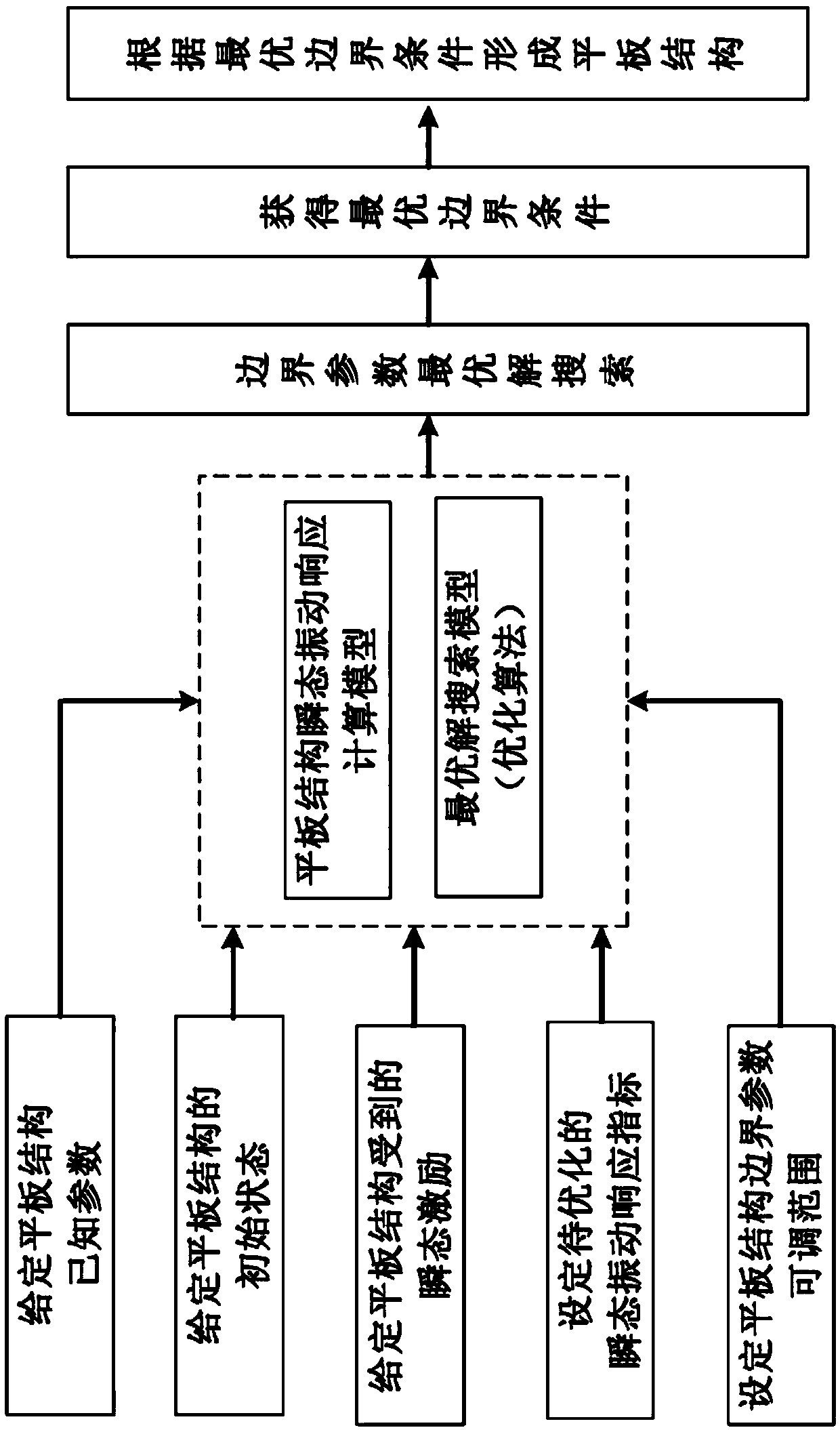
[0033] The specific steps of the method for optimizing the design of a plate structure for improving transient vibration isolation performance in this embodiment are as follows:

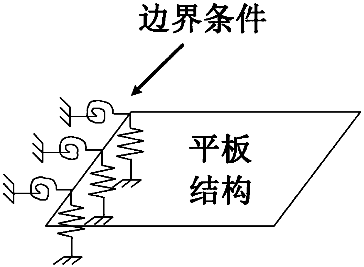
[0034] Step 1. Establish a calculation model for the transient vibration response of a flat plate structure applicable to any boundary conditions:

[0035]

[0036] in, and {δ(t)} are the instantaneous nodal acceleration, instantaneous nodal velocity and instantaneous nodal displacement vector of the plate structure at time t, respectively, Δt is the calculation time step, and {F(t)} is the instantaneous The excitation vector, α and γ are the time integration constants of Newmark method, respectively, and {M}, {C} and {K} are the overall mass matrix, damping matrix and overall stiffness matrix of the flat plate structure, respectively.

[0037] {M} and {K} can be obtained by the finite element method, that is, {M} is obtained by the equivalent mass matrix {M p} e Assembled by the direct stiffn...

Embodiment 2

[0083] The method for optimizing the design of a plate structure for improving transient vibration isolation performance in this embodiment, the specific steps are as follows:

[0084]Step 1. Establish a calculation model of the transient vibration response of the flat plate structure applicable to any boundary conditions. The model is the same as that in Embodiment 1, and will not be repeated here.

[0085] Step 2. Set various known parameters of the plate structure: including plate material, damping factor, size, and thickness. The specific parameter values ​​in this example are shown in the table below:

[0086]

[0087] Table 4

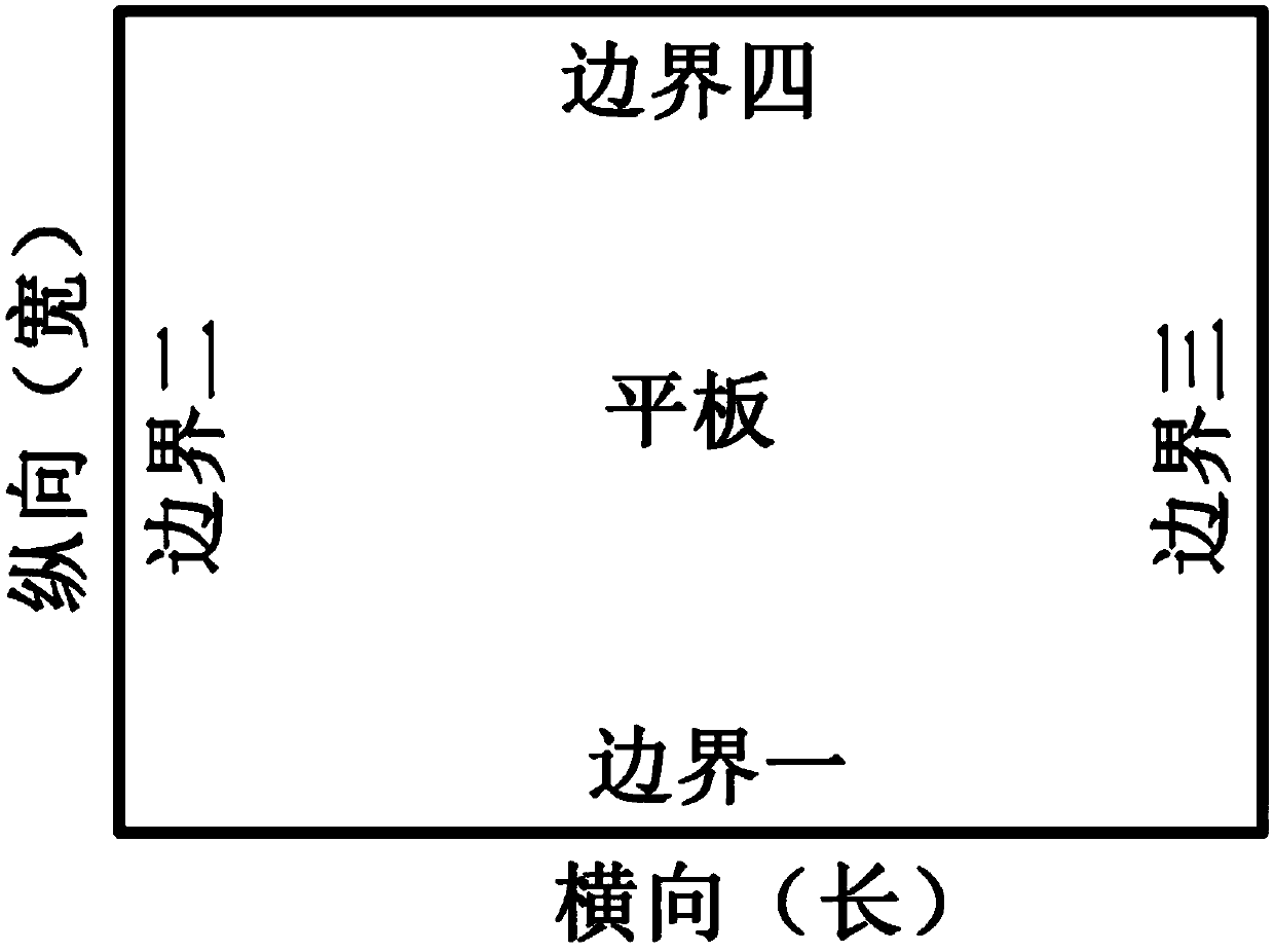
[0088] Step 3. Set the adjustable range of boundary parameters, as shown in the table below:

[0089]

[0090] table 5

[0091] Step 4. The initial state of the plate structure and the transient excitation received are given. The initial state given in this example is The center of the plate is subjected to a transient excitation, and ...


PUM


Abstract

The invention relates to an optimum flat plate structure design method for improving transient vibration isolation performance. The method comprises the following steps of: constructing a flat plate structure transient vibration response calculation model; giving an initial state of a flat plate structure, transient excitation suffered by the flat plate structure, a to-be-optimized transient vibration index and a boundary parameter adjustable range; carrying out optimum solution search by combining known parameters of the flat plate structure and utilizing an optimization algorithm; obtainingan optimum boundary condition of the flat plate structure; and guiding optimum design of the flat plate structure according to the optimum boundary condition. According to the method, the transient vibration isolation performance of flat plate structure can be maximized without changing own parameters of flat plates.

Description

technical field [0001] The invention relates to the technical field of plate structure optimization, in particular to a plate structure optimization design method for improving transient vibration isolation performance. Background technique [0002] Flat plate structure is one of the most common structures in engineering, widely used in shipbuilding and ocean engineering, aerospace engineering, civil engineering, vehicle engineering and other structures. The vibration isolation characteristics of flat plate structures have been paid much attention. It is well known that the boundary installation conditions of flat-plate structures have an important impact on the sound and vibration insulation performance of the structure. In reality, many excitation sources and noise sources have obvious transient characteristics. If the optimization design of boundary conditions can be used to improve the transient vibration isolation performance of the plate structure (such as reducing t...

Claims


Application Information

Patent Timeline
IPC IPC(8): G06F17/50
CPCG06F30/20
Inventor 欧达毅
Owner HUAQIAO UNIVERSITY
Why Eureka
Try Eureka