
Power divider

A power divider and spiral inductor technology, applied in the microwave field, can solve the problems of large volume and weight, high cost, poor stability of the power divider, etc., and achieve the effect of compact structure, high weldability and reduction of overall size.

Inactive Publication Date: 2018-11-06
深圳市永盛微波技术有限公司
View PDF1 Cites 2 Cited by
  • Summary
  • Abstract
  • Description
  • Claims
  • Application Information

AI Technical Summary

Problems solved by technology

[0003] The purpose of the present invention is to provide a power divider, aiming to solve the technical problems of poor stability, relatively large volume and weight, and relatively high cost of the power divider in the prior art

Method used


Image

  • Power divider
  • Power divider
  • Power divider

Examples


Embodiment Construction

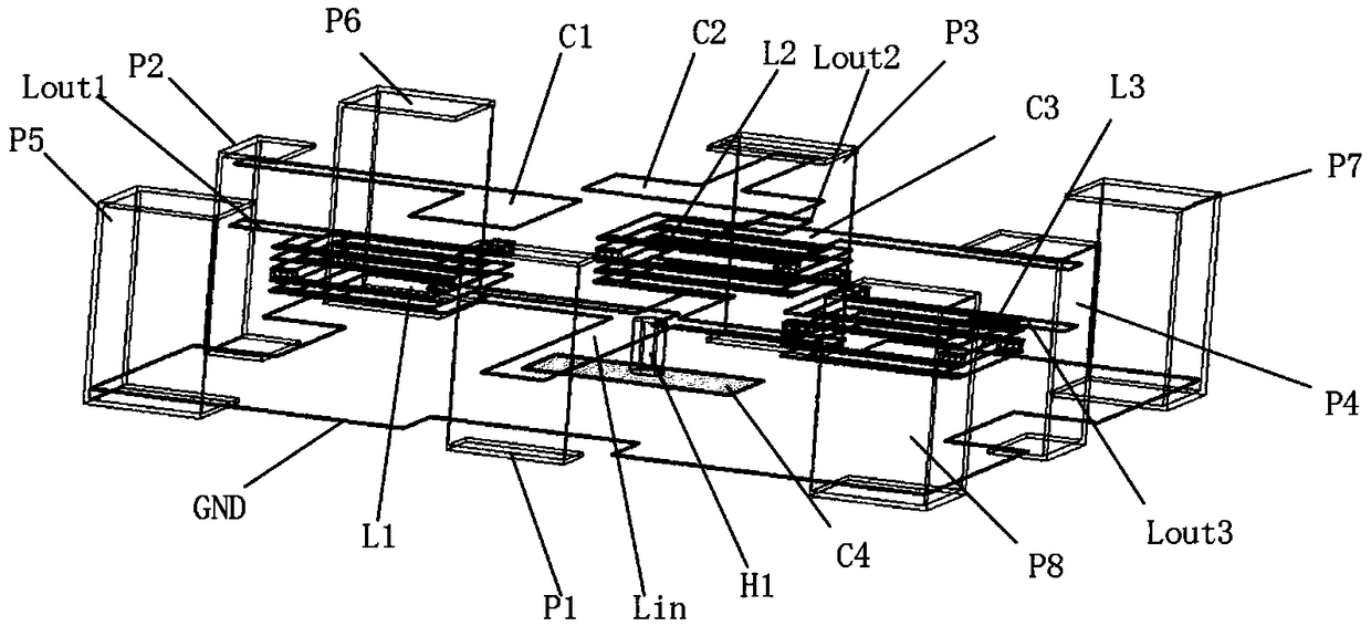
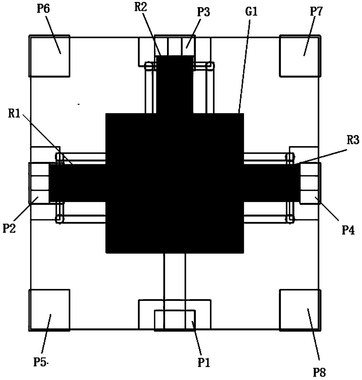
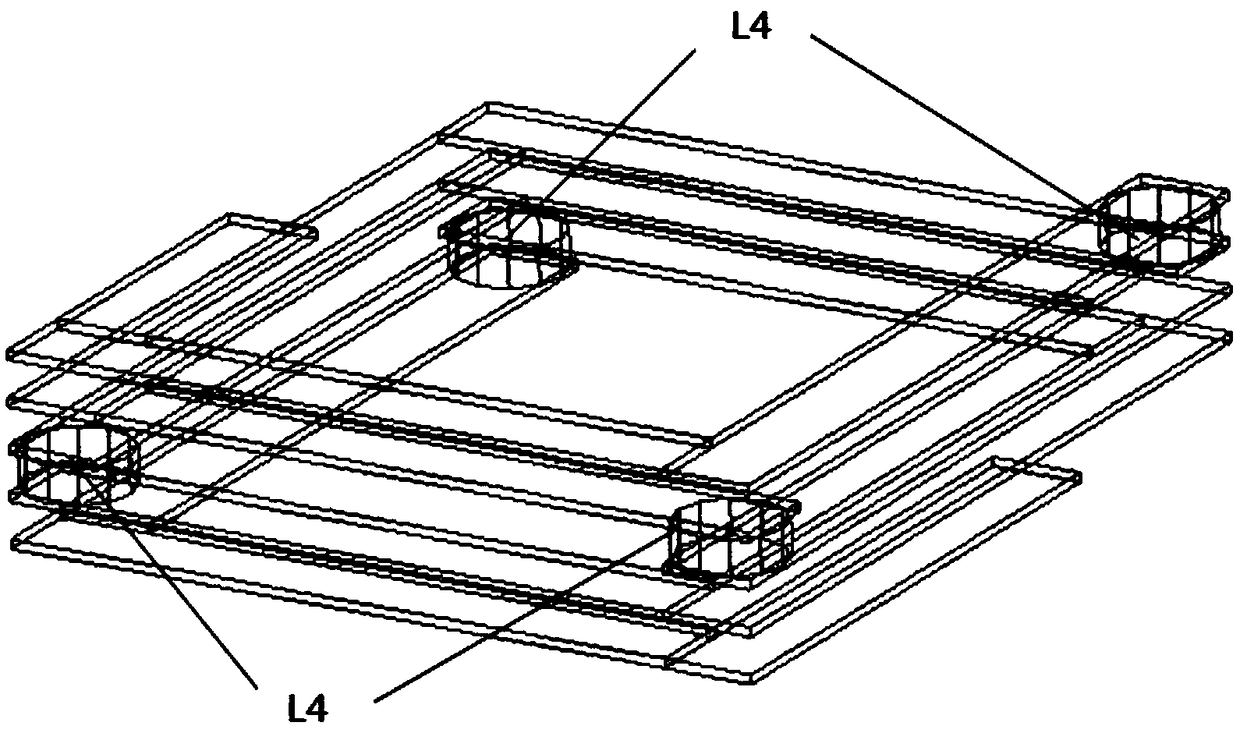
[0045] Such as figure 1 Shown is a schematic diagram of a three-dimensional structure of a power divider of the present invention, figure 2 shown as figure 1 The top view of the power divider includes a three-dimensional structure power divider core component, and the power divider core component includes a lumped capacitor with a compact structure from top to bottom, a square three-dimensional multi-layer spiral structure set The total spiral inductance and the input lead Lin are 3D packaged by LTCC technology to form a power splitter with a compact structure;

[0046]The lumped spiral inductor and the lumped capacitor directly above it constitute three sets of LC impedance matching transformation sections, which can replace the traditional quarter-wavelength transmission line, and can simultaneously achieve higher impedance values ​​while reducing the plane size. At the same time, the matching of the output ports is improved, and the isolation between each port is increas...


PUM


Abstract

A power divider comprises a three-dimensional core component comprising a lump capacitance with a compact structure, a lumped spiral inductor with a square three-dimensional multi-layer screw type structure and input leads Lin from top to bottom. The three parts are packaged in 3D by LTCC technology to form the power divider with a compact structure, and the diameter of the inductance coil is effectively reduced by the lumped spiral inductance with a square three-dimensional multi-layer spiral structure so as to reduce the plane size of the power divider, thereby realizing the compact structure, and the power divider has the characteristics of small volume, light weight and low cost; The lumped spiral inductance and the lumped capacitance directly above the lumped spiral inductance form three sets of LC impedance matching conversion sections, which can replace the traditional quarter wavelength transmission line, simultaneously realize higher impedance value under the condition of reducing the plane size, improve the matching of the output ports, and increase the isolation degree between the ports.

Description

technical field [0001] The invention belongs to the field of microwave technology, in particular to a power divider. Background technique [0002] With the rapid development of miniaturization of mobile communication, satellite communication and national defense electronic systems, high performance, low cost and miniaturization have become the development direction of the microwave / radio frequency field. The performance, size, reliability and cost of power dividers higher requirements have been put forward. In some state-of-the-art defense equipment, the current frequency bands used are already quite crowded, so cutting-edge equipment such as satellite communications are developing towards the millimeter-wave band, and the rapid development of multi-channel multiplexing technology has made the microwave and millimeter-wave band multi-channel power splitters have become the band Critical electronic components in the receive and transmit branches. Contents of the invention ...

Claims


Application Information

Patent Timeline
Patent Type & Authority Applications(China)
IPC IPC(8): H01P5/20
CPCH01P5/20
Inventor 戴永胜陈相治杨茂雅孙超
Owner 深圳市永盛微波技术有限公司
Learn More