Drying device of printer

A technology of drying device and printing machine, applied in printing machine, printing machine, general parts of printing machine, etc., can solve the problems of uncontrollable drying temperature and lack of cooling device, etc.

Pending Publication Date: 2018-11-09
芜湖市华美工艺包装有限公司
View PDF0 Cites 2 Cited by
  • Summary
  • Abstract
  • Description
  • Claims
  • Application Information

AI Technical Summary

Problems solved by technology

[0004] The purpose of the present invention is to overcome the deficiencies of the prior art and provide a printing machine drying device to

Method used


Image

  • Drying device of printer
  • Drying device of printer
  • Drying device of printer

Examples


Embodiment 1

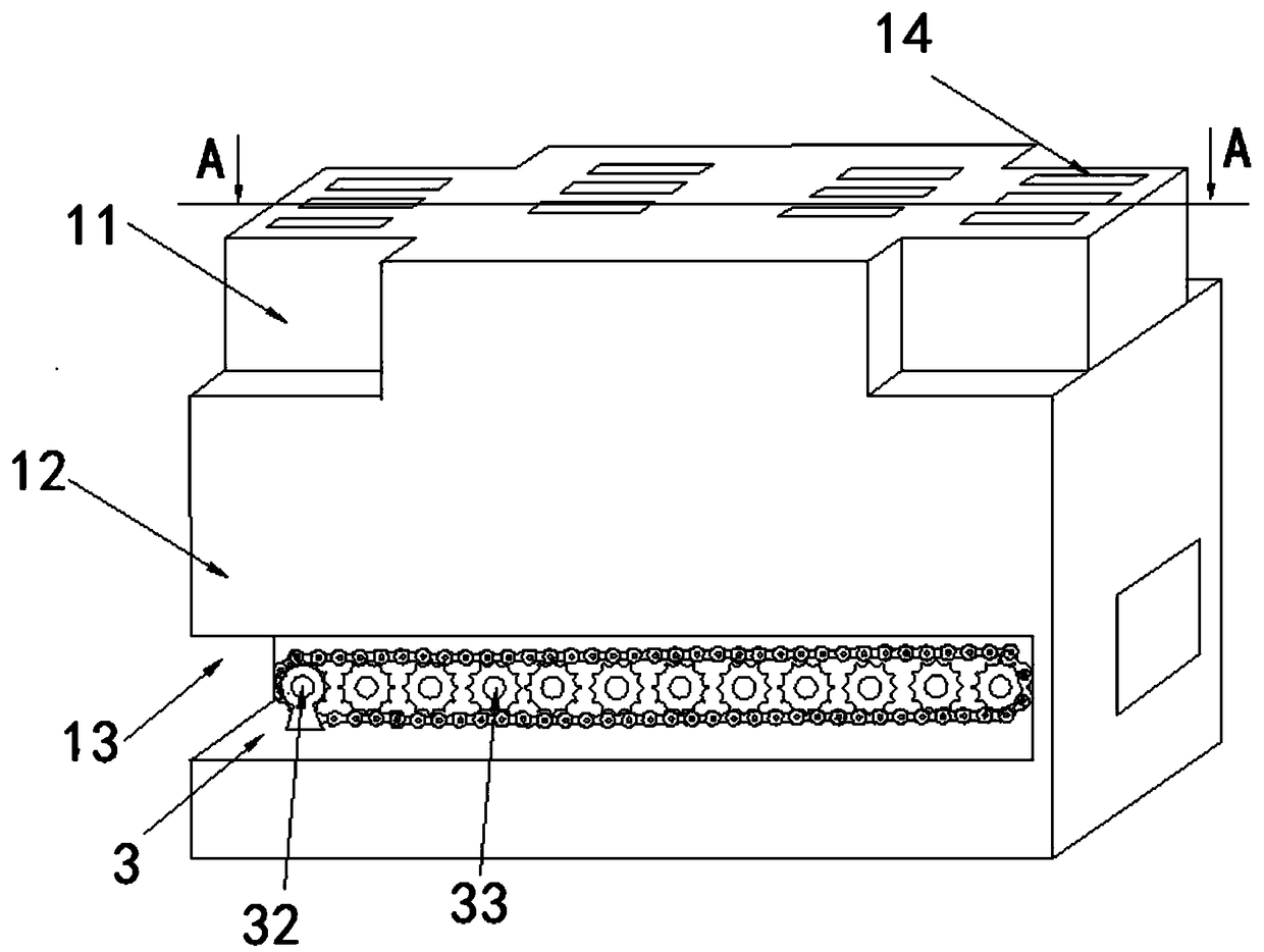
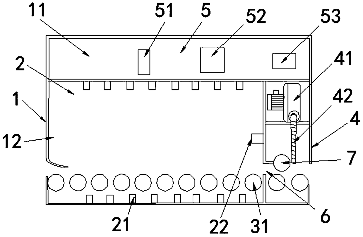
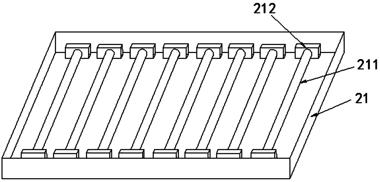
[0019] Embodiment 1 discloses a printing press drying device, such as figure 1 and figure 2 As shown, it includes a box body 1, a heating unit 2, a transmission unit 3, a cooling unit 4 and a control unit 5. Both sides of the box body 1 are respectively provided with a paper inlet and a paper outlet, as image 3 As shown, the heating unit 2 includes a heating element 21, and the heating element 21 is installed inside the box body 1. The box body 1 is divided into a box body top 11 with a "+" shape structure and a box body bottom 12 with a rectangular structure. The box body top 11 is also There are oblong cooling holes 14, and the number of oblong cooling holes 14 is 12. The heating unit 2 and the cooling unit 4 are installed side by side at the bottom of the box body 1, and the heating unit 2 and the cooling unit 4 are separated by a steel plate (not marked in the figure), and a paper transfer channel is opened on the steel plate (not marked in the figure). Hole 6, a circu...

Embodiment 2

[0023] Embodiment 2 discloses a printing machine drying device, which includes a box body 1, a heating unit 2, a transmission unit 3, a cooling unit 4 and a control unit 5. Both sides of the box body 1 are respectively provided with a paper inlet and a paper outlet. The heating unit 2 includes a heating element 21, and the heating element 21 is installed inside the box body 1. The box body 1 is divided into a box body top 11 with a "+" structure and a box body bottom 12 with a rectangular structure. The box top 11 is also provided with a long There are 12 circular cooling holes 14 and 12 oblong cooling holes 14 . The heating unit 2 and the cooling unit 4 are installed side by side at the bottom of the box body 1, and the heating unit 2 and the cooling unit 4 are separated by a steel plate, and a paper transmission hole 6 is opened on the steel plate, and the right side of the paper transmission hole 6 is also A circular pulley 7 is fixed, and the vertical distance between the ...


PUM


Abstract

The invention discloses a drying device of a printer. The drying device comprises a tank, a heating unit, a transmission unit, a cooling unit and a control unit, wherein the tank comprises a tank topand a tank bottom; the tank top is of a crisscross structure; the tank bottom is of a rectangular structure; a groove is formed in one side of the tank bottom; the control unit is mounted at the tanktop; the heating unit is electrically connected with the control unit; the heating unit and the cooling unit are mounted at the tank bottom side by side; the heating unit and the cooling unit are separated by using a steel plate; a paper transferring through hole is formed in the steel plate; the transmission unit is mounted in the groove and adopts the gear chain transmission mode; and the cooling unit is in signal connection with the control unit. As an improvement aimed at the problem that a conventional drying device is uncontrollable in drying temperature and short of a cooling device, the drying device disclosed by the invention has the characteristics that the heating power and the cooling air volume can be adjusted, the efficiency is high, and the adaptability is high.

Description

technical field [0001] The invention relates to the field of offset printing press manufacturing, in particular to a printing press drying device. Background technique [0002] A printing machine is a machine for printing text and images. A modern printing machine is generally composed of plate loading, ink application, embossing, paper feeding and other mechanisms. On the printing machine, the ink is applied manually or by the printing machine to the place where the text and image are on the printing plate, and then directly or indirectly transferred to paper or other substrates to reproduce the same print as the printing plate. With the advancement of science and technology, printing factories have higher and higher requirements for the speed of printing machines, which is a bottleneck for purely mechanical speed improvement. At the same time, the concentration of residual solvents in printing is relatively high, and the pollution of printed matter is relatively serious. ...

Claims


Application Information

Patent Timeline
IPC IPC(8): B41F23/04
CPCB41F23/0426B41F23/0466
Inventor 徐洁
Owner 芜湖市华美工艺包装有限公司
Why Eureka
Try Eureka