
Machining and cutting device for new energy automobile flow guide plate

A new energy vehicle and cutting device technology, applied in metal processing equipment, metal processing machinery parts, manufacturing tools, etc., can solve the problems of changing the chemical properties of metals, wasting water resources, damage to superchargers, etc., to protect the environment and improve The effect of improving work efficiency and improving product qualification rate

Inactive Publication Date: 2018-11-13
WUHU SUNYANG INFORMATION CONSULTATION
View PDF8 Cites 1 Cited by
  • Summary
  • Abstract
  • Description
  • Claims
  • Application Information

AI Technical Summary

Problems solved by technology

[0003] Aluminum alloy material is easily deformed during cutting. The traditional thermal cutting method will change the chemical properties of the metal, which is greatly affected by the thermal effect. When using traditional water jet cutting, the traditional water jet needs a lot of water, which seriously wastes water resources and increases The compressor will generate a lot of heat, and the supercharger may be damaged due to overheating. Therefore, a processing and cutting device for new energy vehicle deflectors that can save water resources and dissipate heat in time is needed

Method used


Image

  • Machining and cutting device for new energy automobile flow guide plate
  • Machining and cutting device for new energy automobile flow guide plate
  • Machining and cutting device for new energy automobile flow guide plate

Examples


Embodiment Construction

[0017] The technical solutions in the embodiments of the present invention will be clearly and completely described below in conjunction with the accompanying drawings in the embodiments of the present invention. Obviously, the described embodiments are only a part of the embodiments of the present invention, rather than all the embodiments. Based on the embodiments of the present invention, all other embodiments obtained by those of ordinary skill in the art without creative work shall fall within the protection scope of the present invention.

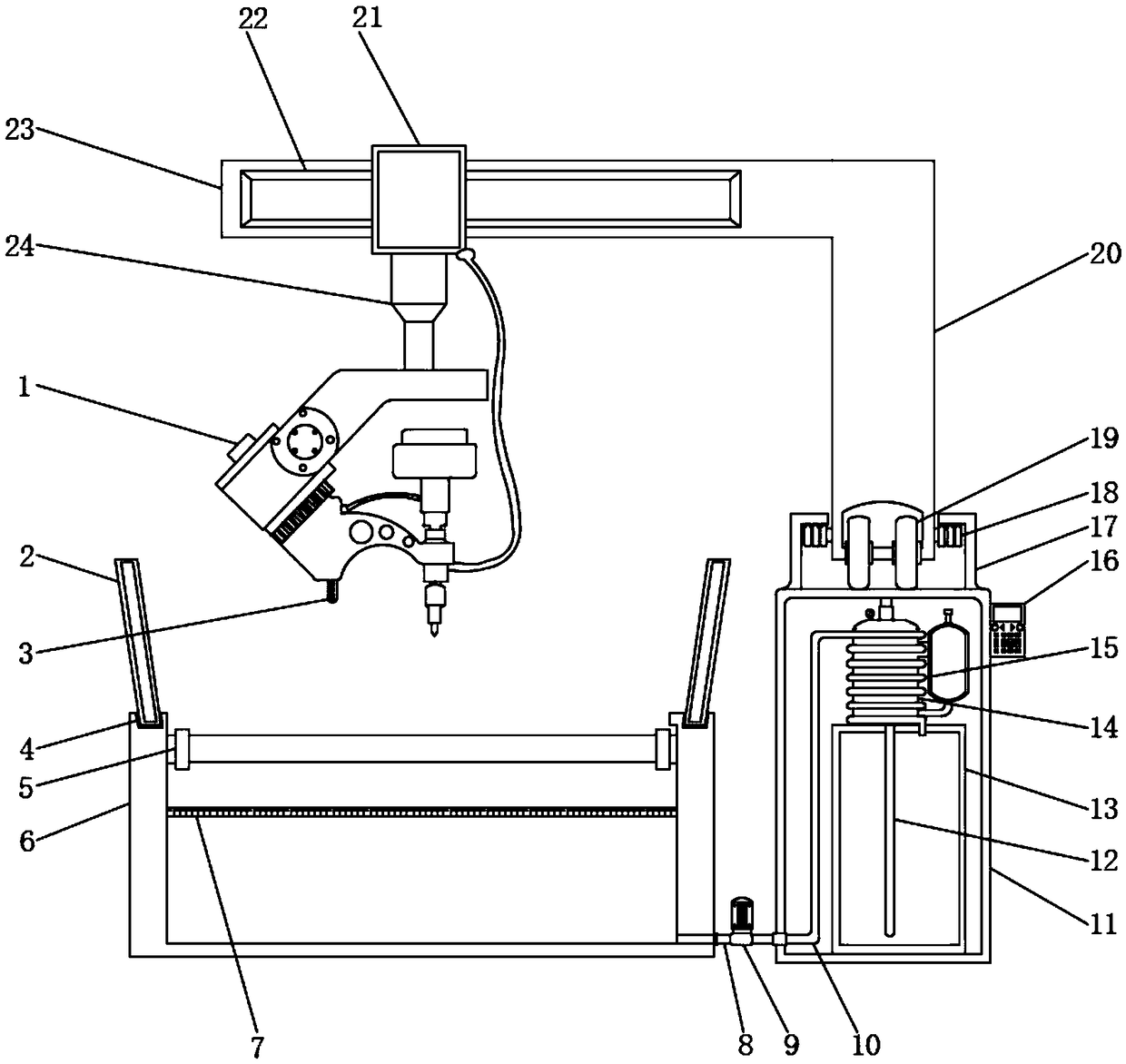
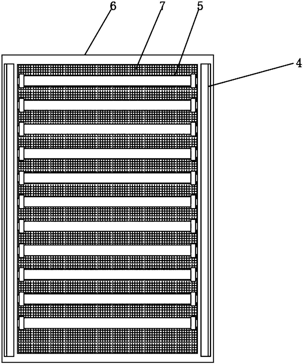
[0018] See Figure 1-3 , A processing and cutting device for the deflector of a new energy vehicle, comprising a water jet 1 and a collecting tank 6. The top surface of the water jet 1 is welded with a telescopic rod 24, and the top face of the telescopic rod 24 is welded with a slider 21, below the water jet 1 A collection tank 6 is provided, and the upper part of the collection tank 6 is provided with a conveying roller 5, below the co...


PUM


Abstract

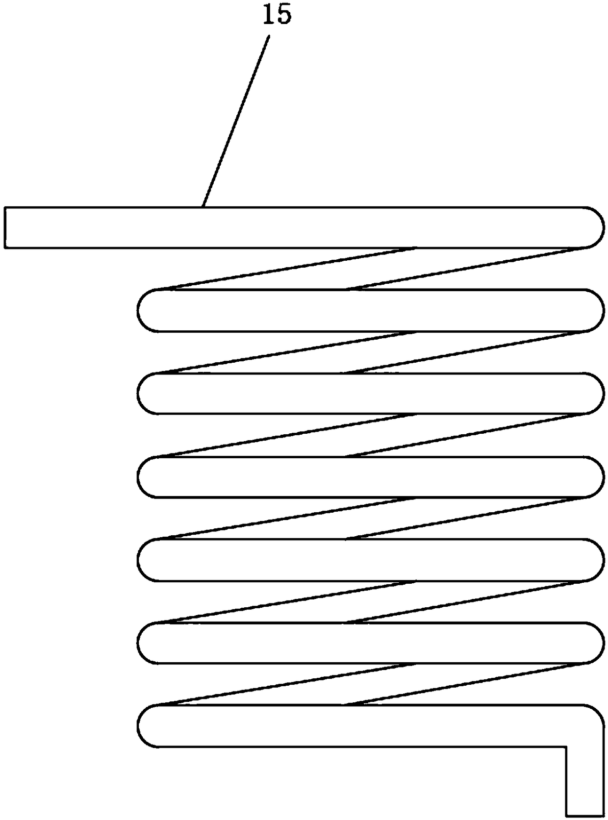
The invention discloses a machining and cutting device for a new energy automobile flow guide plate. The machining and cutting device comprises a water knife and a collecting groove. A telescopic rodis welded to the top face of the water knife, and a sliding block is welded to the top face of the telescopic rod. The collecting groove is arranged below the water knife, and a conveying roller is arranged on the upper portion in the collecting groove. In the machining and cutting device, a self-priming pump and a water cooling pipe are arranged, water filtered by the collecting groove is conveyed into the water cooling pipe by the self-priming pump after being absorbed by a connecting pipe, the water cooling pipe surrounds the peripheral surface of a booster pump, and the water passes through the water cooling pipe to cool the booster pump; meanwhile, the water cooling pipe is connected into a water tank, filtered water is absorbed by the booster pump from the water tank and is conveyedby the self-priming pump to enter the water tank again after being used up and filtered by the collecting groove, and cyclic utilization of water resources is achieved; meanwhile, the circulating water is utilized for carrying out water cooling on the booster pump, water resources are saved, and meanwhile the work efficiency is improved; and the defect that a traditional water knife wastes a largenumber of water resources is remedied.

Description

Technical field [0001] The invention relates to the technical field of deflector processing, in particular to a processing and cutting device for the deflector of a new energy automobile. Background technique [0002] The wind deflector is the scientific name of the wind tail. In addition to increasing the beauty of the car, the tail also has the function of increasing the stability of the car. Especially at high speeds, the airflow through the tail will generate a downforce, thereby reducing the airflow through the body. Lifting power, but the tail wing usually increases the drag coefficient, the deflector is mostly made of lightweight aluminum alloy, and a few luxury cars use carbon fiber. [0003] Aluminum alloy material is easy to deform during cutting. The traditional thermal cutting method will change the chemical properties of the metal and is greatly affected by the thermal effect. When using traditional waterjet cutting, the traditional waterjet requires a lot of water, wh...

Claims


Application Information

Patent Timeline
IPC IPC(8): B23D79/00B23Q11/08B23Q11/12
CPCB23D79/00B23Q11/08B23Q11/12B23Q11/126
Inventor 赵文娟赵文波
Owner WUHU SUNYANG INFORMATION CONSULTATION
Learn More