Overhaul robot used for power station

A technology of robots and robot bases, applied in manipulators, program-controlled manipulators, manufacturing tools, etc., can solve problems such as unclear pictures and poor camera effects, and achieve the effects of improving stability, preventing potential safety hazards, and reducing use costs.

Inactive Publication Date: 2018-11-13
GUANGDONG HONGHUIJING TECH SERVICE CO LTD
View PDF7 Cites 6 Cited by
  • Summary
  • Abstract
  • Description
  • Claims
  • Application Information

AI Technical Summary

Problems solved by technology

[0006] Aiming at the deficiencies of the prior art, the present invention provides a maintenance robot for power stations, which has high monitoring and inspection efficiency, can cope with uneven road surfaces, and does not generate large vibrations and noises when moving, and solves the problem of taking pictures in bad weather. The effect is poor, the picture is not clear, it can prevent collisions from damaging equipment, and it can clean up metal impurities on the road when patrolling
[0008] In order to achieve the high efficiency of the above-mentioned monitoring and inspection, it can deal with uneven roads, avoid large vibrations and noises during exercise, prevent collisions and damage equipment, and can clean up metal impurities on the road surface during patrols, and solve the problem of poor camera effects and blurred images in bad weather. The purpose of the clear problem, the present invention provides the following technical solutions: a maintenance robot for power stations, including a robot base, the outer surface of the front end of the robot base is fixed with a front fender, the front fender The lower end of the lower end of the robot base is fixedly engaged with the outer surface of the lower end of the robot base, and the outer surface of the front end of the front fender is fixedly equipped with a signal lamp and a radar receiver, the signal lamp is located on both sides of the radar receiver, and the front fender The outer surface of the lower end of the plate is fixed with a permanent magnetic adsorption block, the inside of the robot base runs through and extends to both sides to provide a pull-back noise reduction wheel system, and the upper end of the robot base is provided with a self-protection device, and the self-protection device An emergency brake switch is fixedly installed on the outer surface of the upper end of the emergency brake switch, and a platform control room is arranged behind the emergency brake switch, and the platform control room is located on the upper outer surface of the self-protection device. A broadcasting device is fixedly installed on the surface, and the outer surface of the upper end of the platform control room is provided with a movable shaft, and a servo motor is fixedly installed on the upper end of the movable shaft, and an infrared thermal imager is installed on one side of the servo motor. A visible light camera is installed on the side of the servo motor far away from the infrared thermal imager, the upper ends of the infrared thermal imager and the visible light camera are fixedly equipped with a sunshade, and the outer surface of the front end of the visible light camera is provided with an infrared supplementary light Light and wiper, and the wiper is located under the infrared supplementary light, the outer surface of the rear end of the platform control room is fixedly installed with a laser navigation device, the rear of the platform control room is provided with a status light, and the status light is fixedly installed On the outer surface of the upper end of the self-protection device, a radiator, a power switch key and a charging hole are fixedly installed on the outer surface of the rear end of the robot base

Method used


Image

  • Overhaul robot used for power station
  • Overhaul robot used for power station
  • Overhaul robot used for power station

Examples


Embodiment Construction

[0034] The following will clearly and completely describe the technical solutions in the embodiments of the present invention with reference to the accompanying drawings in the embodiments of the present invention. Obviously, the described embodiments are only some, not all, embodiments of the present invention. Based on the embodiments of the present invention, all other embodiments obtained by persons of ordinary skill in the art without making creative efforts belong to the protection scope of the present invention.

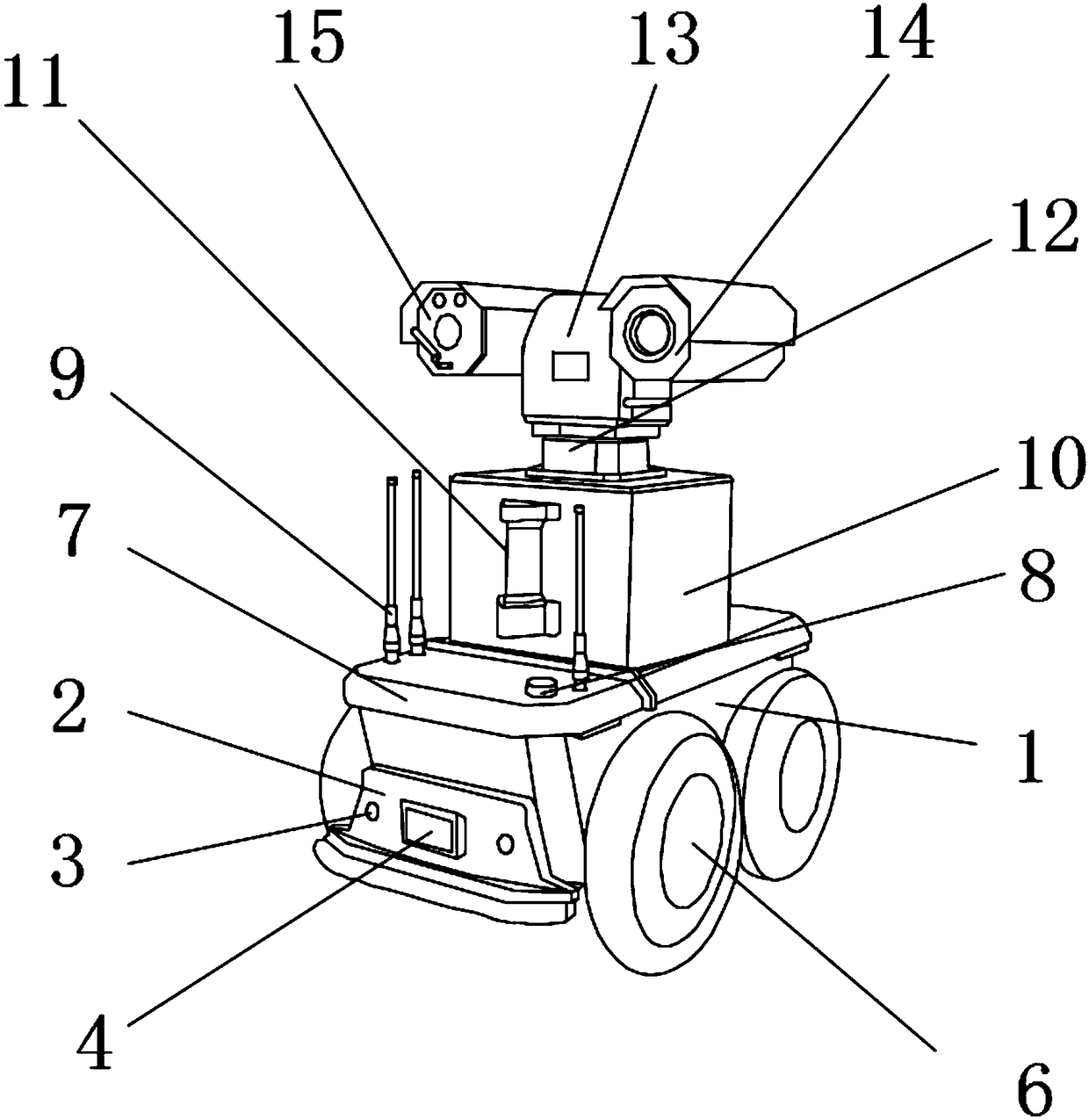
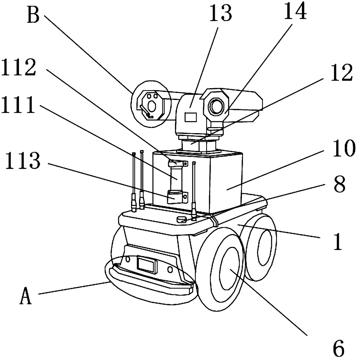
[0035] see Figure 1-8, a maintenance robot for a power station, comprising a robot base 1, a front fender 2 is fixedly installed on the outer surface of the front end of the robot base 1, and the lower end of the front fender 2 is fixedly engaged with the outer surface of the lower end of the robot base 1 Then, the outer surface of the front end of the front fender 2 is fixedly equipped with a signal lamp 3 and a radar receiver 4, the signal lamp 3 is located...


PUM


Abstract

The invention relates to the technical field of robot devices, and discloses an overhaul robot used for a power station. The overhaul robot comprises a robot base. A front fender is fixedly installedon the outer surface of the front end of the robot base. The lower end of the front fender is fixedly connected with the outer surface of the lower end of the robot base in a clamping manner. Signal lamps and a radar receiver are fixedly installed on the outer surface of the front end of the front fender. The signal lamps are located on the two sides of the radar receiver. A return noise reducingwheel system is arranged in the robot base in the manner that the return noise reducing wheel system penetrates the inner portion of the robot base and extends to the two sides. The overhaul robot used for the power station can automatically patrol in the power station and can clear away metal impurities on the ground during patrolling, it can be ensured that pictures of camera shooting devices are clear in rainy and foggy weather, the problem that due to the adoption of rigid wheels, great impact and noise are generated during movement is avoided, and device damage caused by collision can beeffectively prevented when the robot works.

Description

technical field [0001] The invention relates to the technical field of robot equipment, in particular to a maintenance robot for power stations. Background technique [0002] The power station is a place to transmit and change voltage, and is an important facility of the power grid. Therefore, ensuring the safe operation of the power station is of great significance to the entire power grid. In order to monitor the operating status of many equipment inside the power station, it is necessary to monitor and inspect the power station regularly. . [0003] Traditional power station monitoring and inspections generally use personnel scheduling. Because manual inspections consume manpower and take a long time, current power station inspections generally use unattended or few people on duty. Among them, maintenance robots are used to monitor and control the power station. Inspection and maintenance robots can detect thermal defects of power equipment, foreign object suspension and...

Claims


Application Information

Patent Timeline
Patent Type & Authority Applications(China)
IPC IPC(8): B25J5/00B25J9/16B25J19/00
CPCB25J5/007B25J9/1664B25J19/00B25J19/0091
Inventor 陈杰
Owner GUANGDONG HONGHUIJING TECH SERVICE CO LTD
Why Eureka
Try Eureka