An outrigger type steel pipe pile and its construction method

A steel pipe pile and arm type technology, which is applied in sheet pile wall, foundation structure engineering, construction and other directions, can solve the problems of low bearing capacity and smooth side wall, and achieve the effect of improving strength, convenient operation and expanding the scope of application.

Active Publication Date: 2020-12-22
SHANDONG UNIV OF SCI & TECH
View PDF1 Cites 0 Cited by
  • Summary
  • Abstract
  • Description
  • Claims
  • Application Information

AI Technical Summary

Problems solved by technology

[0006] The purpose of the present invention is to provide an outrigger type steel pipe pile, which can solve the technical problems of smooth side walls and low bearing capacity of existing steel pipe piles, so that the side friction resistance and bearing capacity are greatly improved, and can be applied to building foundations reinforcement

Method used


Image

  • An outrigger type steel pipe pile and its construction method
  • An outrigger type steel pipe pile and its construction method
  • An outrigger type steel pipe pile and its construction method

Examples


Embodiment 1

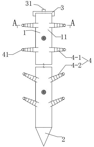
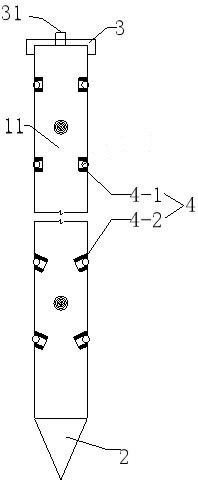
[0040]Such asFigure 1-3 Shown:

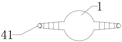
[0041]An outrigger steel pipe pile, comprising a pile body 1 and a pile tip 2. The pile body 1 is a steel pipe structure, the pile tip 2 is a conical structure with a closed bottom, and the pile body 1 and the pile tip 2 are integrally formed The inside of the pile body 1 is a cavity structure, and the pile body 1 is connected with an outrigger 4 that can extend to the outside of the pile body 1 and insert into the soil; after the outrigger is inserted into the soil, the steel pipe pile is greatly increased The lateral friction resistance and bearing capacity meet the requirements of building foundation reinforcement and expand the scope of application;

[0042]The extension arm 4 is a hollow structure with one end closed and the other end open, and the cavity communicates with the hollow structure through an opening; the extension arm 4 includes a first extension arm 4-1 and a first extension arm 4-1 arranged perpendicular to the pile body 1 The second ex...

Embodiment 2

[0054]Embodiment 2 is the construction method of embodiment 1. The specific method is: a construction method of outrigger steel pipe pile, and the specific steps are as follows:

[0055]1) Provide an outrigger steel pipe pile as described in Example 1;

[0056]2) Set the line to determine the pile position, use the lifting ring to suspend the outrigger steel pipe pile directly above the pile position, and aim the pile tip at the middle position of the pile position;

[0057]3) Start the pile driver and slowly insert the outrigger steel pipe pile into the foundation;

[0058]4) When the pile body reaches a predetermined depth, cover the pile cover 3, and use a high-pressure air pump to inject high-pressure gas into the cavity through the high-pressure inflation hole 31 on the pile cover 3, and stabilize the pressure for 13-18 minutes to ensure the extension Arm 4 is fully extended and inserted into the soil;

[0059]5) Remove the pile cover 3 and the high-pressure air pump, insert a grouting pipe i...


PUM


Abstract

The invention relates to a semi-girder type steel pipe pile and a construction method thereof. The semi-girder type steel pipe pile comprises a pile body and a pile point, the pile body is of a steelpipe structure, and the semi-girder type steel pipe pile is characterized in that pile point is of a conical structure with the sealed bottom, the pile body and the pile point are integrally formed, acavity structure is arranged in the pile body, and the pile body is connected with a semi-girder capable of stretching out of the pile body and being inserted into soil; and the semi-girder is of a hollow structure with a sealed end and an open end, and a cavity communicates with the hollow structure through an opening; and the semi-girder comprises a first semi-girder body perpendicular to the pile body and a second semi-girder body inclined relative to the pile body. The friction resistance and bearing capacity of the steel pipe pile are greatly improved, and the semi-girder type steel pipepile is suitable for reinforcing a building foundation.

Description

Technical field[0001]The invention relates to the technical field of steel piles, in particular to an outrigger steel pipe pile and a construction method thereof.Background technique[0002]Engineering piles are divided into concrete piles, steel piles and composite material piles according to the pile body material;[0003]Steel pipe piles are a kind of steel piles, which have the advantages of light weight and high bearing capacity. At present, they are widely used in marine engineering. However, the sidewalls of steel pipe piles are smooth and the friction coefficient of the pile body is low. In view of this, steel pipe columns are rarely used for the reinforcement of building foundations.[0004]In response to the above-mentioned shortcomings, the Chinese Patent (Publication No.: CN106869106A) proposes a method of welding side-wing steel pipe piles to reinforce the foundation, which uses side wings when the length of ordinary steel pipe piles reaches two-thirds of the designed pile le...

Claims


Application Information

Patent Timeline
Patent Type & Authority Patents(China)
IPC IPC(8): E02D5/48E02D5/50E02D5/62
CPCE02D5/48E02D5/50E02D5/62
Inventor 王颖胡振华李勇李允
Owner SHANDONG UNIV OF SCI & TECH
Why Eureka
Try Eureka