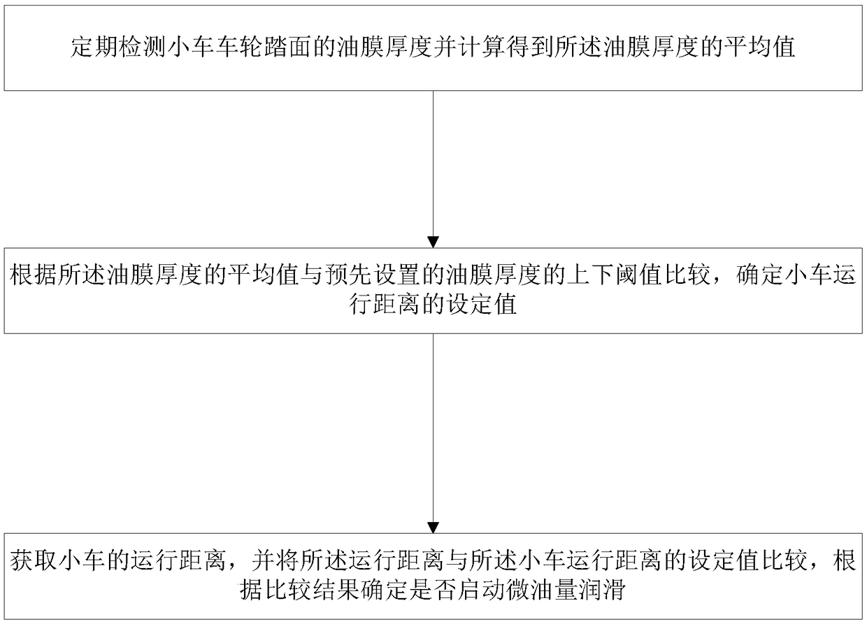
Tiny-oil-amount lubrication method and device
A technology of lubricating device and micro-oil quantity, applied in the direction of engine measuring device, lubricating parts, engine lubrication, etc., can solve problems such as rail gnawing, and achieve the effect of solving environmental pollution problems, reducing running resistance and reducing friction coefficient
- Summary
- Abstract
- Description
- Claims
- Application Information
AI Technical Summary
Problems solved by technology
Method used
Image
Examples
Embodiment 1
[0028] During the deviation process of the wheels of the trolley towed by the quay crane, each wheel train will generate additional axial force due to the difference in deflection angle. This axial force will increase with the increase of the deviation displacement, and force the trolley Buckling deformation occurs in the steel structure of the trolley frame, and when the axial force reaches or exceeds the friction force between the wheel and the track, the wheel of the trolley axially slides back to the initial position. Repeatedly, the steel structure of the trolley frame is subjected to long-term alternating loads, and fatigue cracking is prone to occur.
[0029] During the process of the trolley wheel gnawing on the rail, there is a strong extrusion effect between the wheel rim and the side of the track, and because of the high friction coefficient between the wheel and the track, it produces a great running resistance to the operation of the equipment. According to the me...
Embodiment 2
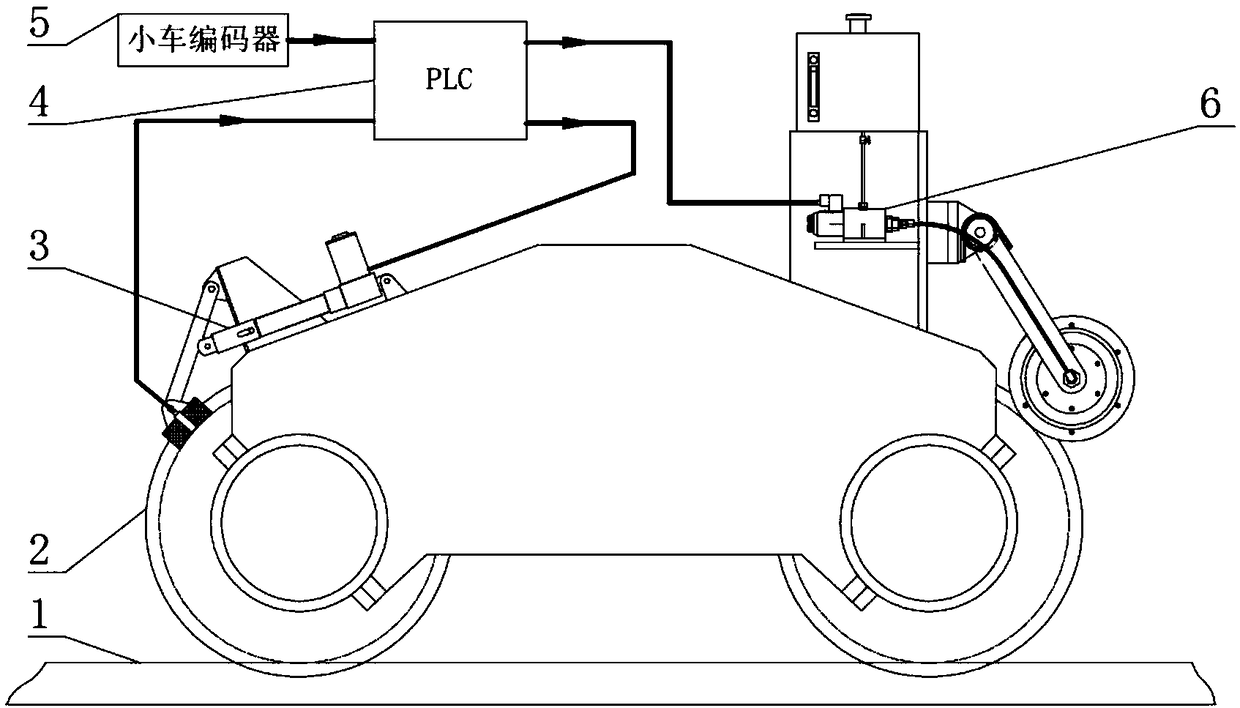
[0040] Such as figure 2 As shown, the present invention provides a minimum oil quantity lubrication device, including: an oil film thickness detection unit 3 , a control unit 4 , a trolley encoder 5 and a minimum oil quantity lubrication coating unit 6 . For convenience of description, the figure also includes a track 1 and a trolley wheel 2 .
[0041] The oil film thickness detection unit 3 is electrically connected with the control unit 4, and is used to receive the work order of the control unit 4, detect the oil film thickness of the trolley wheel tread and send the signal of the oil film thickness to the control unit 4;
[0042] The dolly encoder 5 is electrically connected to the control unit 4, and is used to collect pulse signals in the running of the dolly and send the pulse signals to the control unit 4;
[0043] The micro-oil lubrication coating unit 6 is electrically connected to the control unit 4, receives the pulse signal from the control unit 4 and outputs lu...
Embodiment 3
[0055] Such as Figure 6 As shown, the micro oil volume pump includes: electromagnetic coil 17, ejector rod 18, valve seat 19, plunger 20, oil inlet chamber 21, return spring 22, oil hole 23, plunger sleeve 24, working chamber 25, check valve 26, oil outlet cavity 27 and compression spring 28.
[0056] The electromagnetic coil 17 is installed on the end surface of the valve seat 19, and the ejector rod 18 is installed between the inner iron core of the electromagnetic coil 17 and the plunger 20, arranged coaxially. The plunger 20 is assembled in the sliding sleeve of the plunger sleeve 24, and there is a good fit gap between the two to seal the oil. The return spring 22 is assembled between the plunger sleeves 24 of the plunger 20 . The one-way valve 26 at the rear end of the plunger sleeve 24 closes the oil outlet under the action of the compression spring 28 , and now the oil in the working chamber 25 communicates with the oil inlet chamber 21 through the oil hole 23 . Th...
PUM
 Abstract
Description
Claims
Application Information
 - R&D
- Intellectual Property
- Life Sciences
- Materials
- Tech Scout
- Unparalleled Data Quality
- Higher Quality Content
- 60% Fewer Hallucinations
Browse by: Latest US Patents, China's latest patents, Technical Efficacy Thesaurus, Application Domain, Technology Topic, Popular Technical Reports.
© 2025 PatSnap. All rights reserved.Legal|Privacy policy|Modern Slavery Act Transparency Statement|Sitemap|About US| Contact US: help@patsnap.com


