
Radio altimeter of digitized pulse system

A radio altimeter and pulse technology, applied in radio wave measurement systems, radio wave reflection/re-radiation, utilization of re-radiation, etc. altimetry results and other issues, to achieve the effect of ensuring reliability, high reliability ranging, and ensuring high measurement accuracy

Pending Publication Date: 2018-11-13
SHAANXI CHANGLING ELECTRONICS TECH
View PDF0 Cites 11 Cited by
  • Summary
  • Abstract
  • Description
  • Claims
  • Application Information

AI Technical Summary

Problems solved by technology

[0006] With more and more equipment equipped on high-speed and high-mobility aircraft such as aircraft and missiles, the electromagnetic environment is becoming increasingly complex, and most aircraft need to fly in formation. Each aircraft is equipped with at least one radio altimeter. There is interference between them, and there is also the same-frequency interference of other airborne radars. When using the analog signal tracking method to measure height, because the analog tracking circuit cannot effectively identify the echo signal or noise signal of the aircraft, other aircraft, if the multi-aircraft formation During flight, the radio altimeter on an aircraft may mistakenly track the echo signals of other radars or track noise signals. This wrong tracking will lead to the output of wrong altimetry results, which will affect the safety and normal tracking of aircraft formation flight

Method used


Image

  • Radio altimeter of digitized pulse system
  • Radio altimeter of digitized pulse system
  • Radio altimeter of digitized pulse system

Examples


Embodiment Construction

[0029] The present invention will be described in detail below in conjunction with the accompanying drawings.

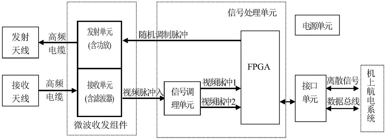
[0030] refer to figure 1 , The present invention includes a receiving antenna, a transmitting antenna, a high-frequency cable for the receiving antenna, a high-frequency cable for the transmitting antenna, a microwave transmitting unit, a microwave receiving unit, a signal processing unit, an interface unit and a power supply unit. The microwave transmitting unit generates a 4300MHz high-frequency pulse signal under the control of the random trigger pulse generated by the signal processing unit, which is transmitted by the transmitting antenna through a high-frequency cable to the transmitting antenna and radiated to the ground. The receiving antenna transmits the echo signal received by the receiving antenna to the microwave receiving unit through the high-frequency cable, and the microwave receiving unit controls the gain of the echo signal under the control of the...


PUM


Abstract

The invention discloses a radio altimeter of a digitized pulse system. The radio altimeter of a digitized pulse system mainly solves the problem that the prior art is easy to encounter cofrequency andextraneous radio frequency interference when a plurality of altimeters are used. The radio altimeter of a digitized pulse system includes transmitting and receiving antennas, a microwave transmissionunit, a microwave receiving unit, a signal processing unit, an interface unit and a power supply unit, wherein the signal processing unit is formed by an FPGA and a signal conditioning circuit; the FPGA is provided with various functional modules for pulse sequence generation, signal detection and tracking, altitude calculation, control of gains of the microwave receiving unit, control parameters, interfaces and self-checking of altitude; and the signal conditioning circuit generates two channels of video pulses with different amplitudes, and the first channel of video pulse is sent to a signal detection and tracking module to perform signal tracking and calculate the altitude, and the second channel of pulse is sent to an AGC gain control module to control gains of the microwave receiving unit and stabilize the video pulse amplitude. The radio altimeter of a digitized pulse system can avoid signal interference from other planes when the local altimeter is used, can improve the altitude measuring stability for multi-plane formation, and can be used for aerospace aircrafts.

Description

technical field [0001] The invention belongs to the technical field of radar distance measurement, and in particular relates to a radio altimeter, which can be used for high-precision and high-stability tracking measurement of flight altitude in multi-aircraft formation and complex environment in aerospace and missile aircraft. Background technique [0002] The radio altimeter is a kind of ranging radar, which can measure the real-time altitude of high-speed flying equipment such as aircraft or missiles. FM continuous wave system and pseudo-code continuous wave altimetry system. [0003] The working principle of the pulse system altimeter is: the transmission pulse is generated by the pulse generation circuit, the pulse signal is modulated to the radio frequency by the microwave transmission unit, and radiated to the ground or water surface by the transmission antenna, and the radio frequency signal returned by the ground enters the microwave receiving system through the rec...

Claims


Application Information

Patent Timeline
Patent Type & Authority Applications(China)
IPC IPC(8): G01S13/08G01S13/88
CPCG01S13/08G01S13/882
Inventor 罗维闫锦丽孟宝占郭葆泉郝院坐刘小龙张波涛
Owner SHAANXI CHANGLING ELECTRONICS TECH
Learn More