
Brush direct-current motor

A technology of brushed DC motors and machine bases, applied in the direction of electrical components, electromechanical devices, electric components, etc., can solve the problems of complex structure of brushed DC motors, troublesome disassembly and assembly, troublesome assembly and disassembly, etc., and achieve low loss , Reduce vibration, easy to disassemble

Inactive Publication Date: 2018-11-13
杭州翱月科技有限公司
View PDF0 Cites 0 Cited by
  • Summary
  • Abstract
  • Description
  • Claims
  • Application Information

AI Technical Summary

Problems solved by technology

[0003] When the existing brushed DC motor is in use, the body heats up seriously, and it is easy to burn out the motor after long-term uninterrupted use. In addition, during the working process of the motor, the vibration of the motor is relatively serious, and other heavy objects are often required to be pressed on it, which is troublesome and the motor is easily damaged. Separated from heavy objects; in addition, the structure of the brushed DC motor is complicated, and it is troublesome to assemble and disassemble, especially the disassembly and assembly between the base and the stator.

Method used


Image

  • Brush direct-current motor
  • Brush direct-current motor
  • Brush direct-current motor

Examples


Embodiment Construction

[0016] The present invention will be further described below in conjunction with the accompanying drawings.

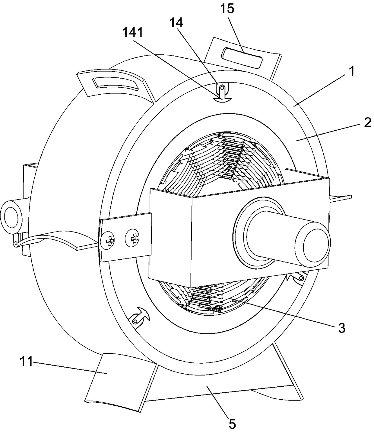
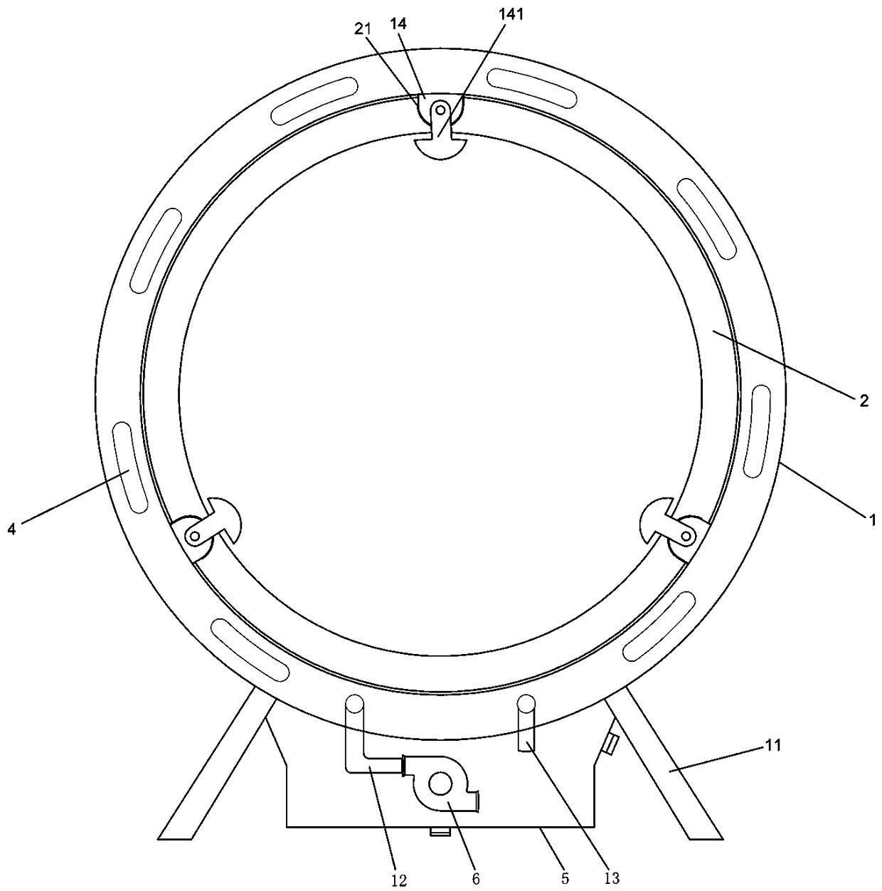
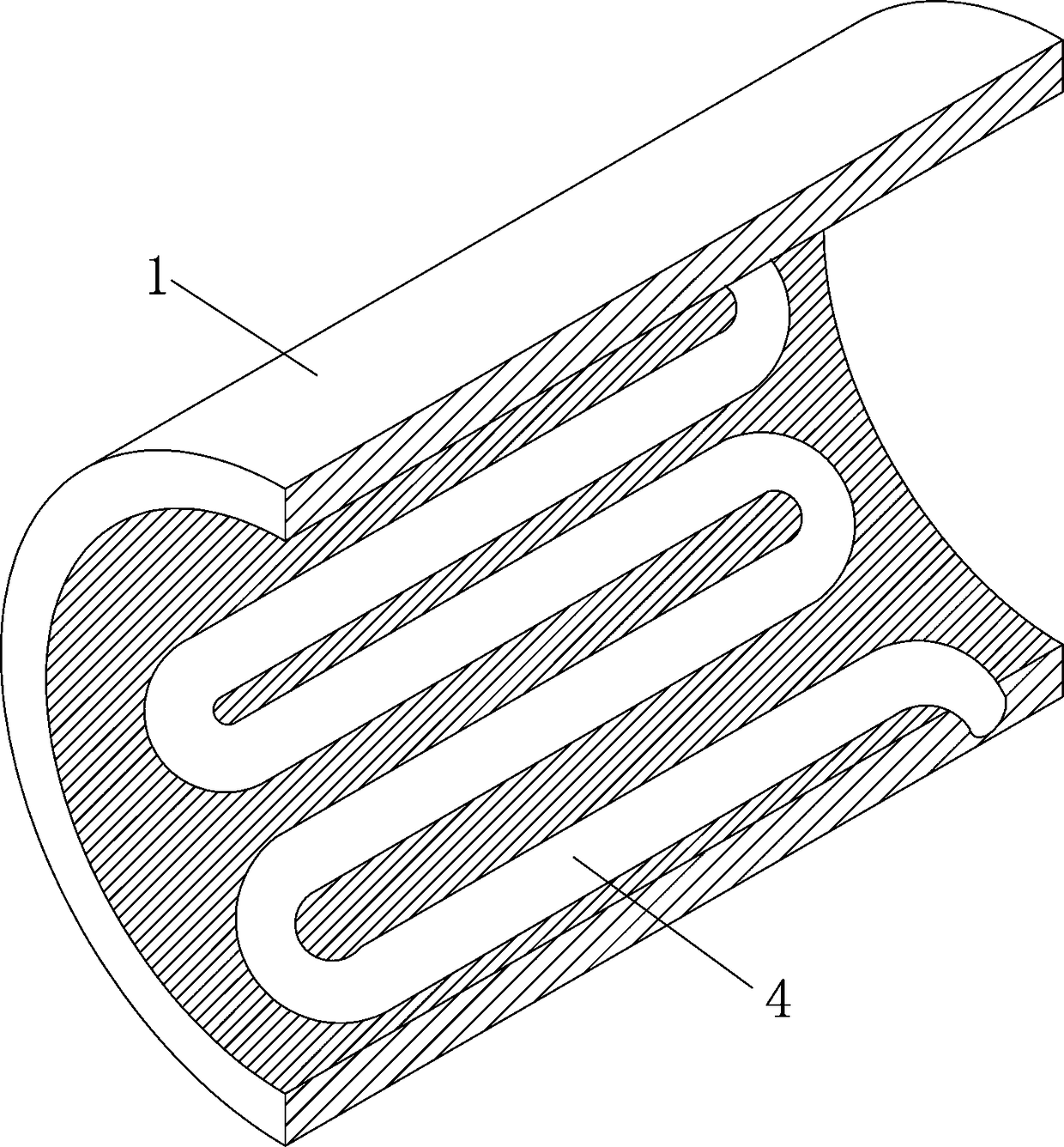
[0017] A brushed DC motor such as Figure 1 to Figure 4 As shown, it includes a base 1, a stator core 2 and a rotor 3, the stator core 2 is in the shape of a ring column, the rotor 3 is embedded in the stator core 2, the base 1 is in the shape of a ring column, and The lower end is fixed with feet 11, and the base 1 is sleeved on the outer surface of the stator core 2; the inner wall of the base 1 is provided with a serpentine water passage 4 in the circumferential direction, and the bottom of the base 1 A water inlet pipe 12 and an outlet pipe 13 respectively connected to the head end and the end of the water passage 4 are provided, and a water storage tank 5 is fixed on the legs 11, and the water storage tank 5 is provided with a The micro water pump 6 that water pipe 12 is connected, the outlet end of described water outlet pipe 13 is communicated with water storag...


PUM


Abstract

The invention relates to a brush direct-current motor. The brush direct-current motor comprises a base, a stator core and a rotor, the stator core is shaped in a circular column, and the rotor is embedded into the stator core. The brush direct-current motor is characterized in that the base is shaped in a circular column and arranged on an outer surface of the stator core in a sleeving manner, support legs are fixedly at the lower end of the base, a snakelike water flow channel is circumferentially formed in a wall of the base, a water inlet tube and a water outlet tube which are respectivelycommunicated with a head end and a tail end of the snakelike water flow channel are arranged at the bottom end of the base, a water storage tank is fixed on the support legs, and a miniature water pump connected with the water inlet tube is arranged in the water storage tank. Through combination of the snakelike water flow channel in the wall of the base and the miniature water pump in the water storage tank at the bottom of the base, water in the water storage tank can be pumped into the snakelike water flow channel and then is enabled to circulate between the water flow channel and the waterstorage tank, so that high temperature generated during working of the motor can be reduced, and on the other hand, weight of the motor can be increased by adding water into the water storage tank fixed at the bottom of the base, and vibration generated during working of the motor can be alleviated.

Description

technical field [0001] The invention relates to the technical field of motors, in particular to a brushed DC motor. Background technique [0002] The basic components of a brushed DC motor include the frame, stator, rotor, brushes and commutator. The stator includes a shell and an iron body for generating the main magnetic field. The rotor includes a rotating shaft, steel sheets and windings wound on the steel sheets. The commutator is sleeved at the input end of the rotating shaft. The electric energy of the DC power supply passes through the brushes and the commutator in turn. The commutator enters the winding in the rotor to generate armature current, and the magnetic field generated by the armature current interacts with the main magnetic field to generate electromagnetic torque, which makes the motor rotate and then drive the load. [0003] When the existing brushed DC motor is in use, the body heats up seriously, and it is easy to burn out the motor after long-term un...

Claims


Application Information

Patent Timeline
Patent Type & Authority Applications(China)
IPC IPC(8): H02K9/19H02K5/20H02K5/24
CPCH02K9/19H02K5/20H02K5/24
Inventor 王沛刘汝策
Owner 杭州翱月科技有限公司
Learn More