C-shaped steel machining equipment for steel structures

A technology for processing equipment and C-shaped steel, applied in metal processing equipment, shearing machine equipment, metal sawing equipment, etc., can solve the problems of high labor intensity, tool damage, long time consumption, etc., to reduce labor intensity and improve work. Efficiency, the effect of incision leveling

Active Publication Date: 2018-11-16
河南中装建设集团有限公司
View PDF5 Cites 6 Cited by
  • Summary
  • Abstract
  • Description
  • Claims
  • Application Information

AI Technical Summary

Problems solved by technology

[0003] In order to solve the above problems, the present invention provides a C-shaped steel processing equipment for steel structures, which can solve the need for manual cutting when cutting C-shaped steel, the process is cumbersome and complicated, and the existing cutting tools are easy to deviate from the position when cutting, making the incision uneven, and The surface of the C-shaped steel may be deformed during the cutting process. The existing tools may cause damage to the tool when directly cutting the C-shaped steel. The process takes a long time, has high labor intensity and low efficiency. It does not deviate from the position, the cut is flat, and the automatic compaction ensures that the C-shaped steel surface does not deform during the cutting process. The tool is protected during cutting, no manual operation is required, the time is short, and it has the advantages of simple operation, low labor intensity and high work efficiency.

Method used


Image

  • C-shaped steel machining equipment for steel structures
  • C-shaped steel machining equipment for steel structures
  • C-shaped steel machining equipment for steel structures

Examples


Embodiment Construction

[0022] In order to make the technical means, creative features, goals and effects achieved by the present invention easy to understand, the present invention will be further described below in conjunction with specific illustrations. It should be noted that, in the case of no conflict, the embodiments in the present application and the features in the embodiments can be combined with each other.

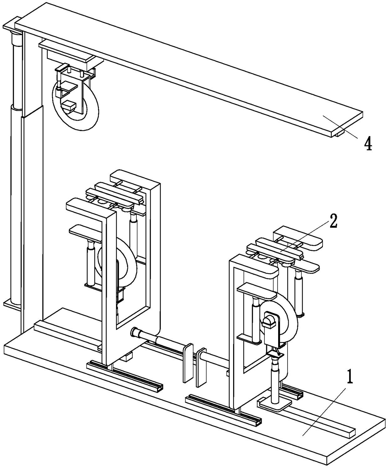
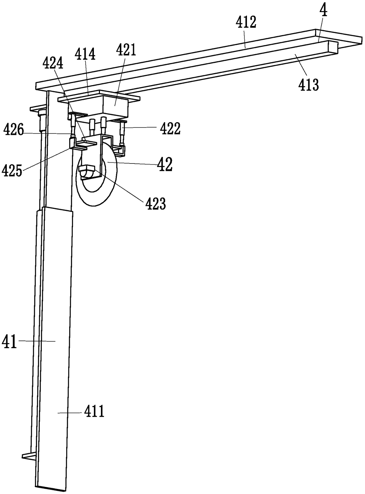
[0023] Such as Figure 1 to Figure 4 As shown, in order to achieve the above object, the present invention adopts the following technical solutions: a C-shaped steel processing equipment for steel structure, including a main board 1, two compacting and cutting devices 2 and an upper end cutting device 4, and the middle part of the upper end of the main board 1 is installed Two compacting and cutting devices 2 are arranged, and an upper end cutting device 4 is installed on the left end of the main board 1 .

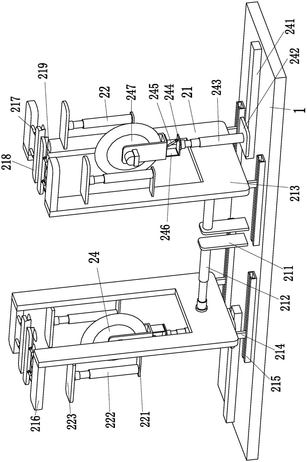
[0024]The compacting and cutting device 2 includes a lower end compacting m...


PUM


Abstract

The invention relates to C-shaped steel machining equipment for steel structures. The equipment comprises a main plate, two compaction cutting devices and an upper end cutting device; the two compaction cutting devices are mounted at the middle part of the upper end of the main plate; and the upper end cutting device is mounted at the left end of the main plate. The C-shaped steel machining equipment can solve the problems that manual cutting is needed in an existing cutting mode of C-shaped steel, uneven incisions are caused due to the fact that a traditional cutting tool is likely to deviateduring cutting, possible deformation of C-shaped steel surfaces is likely to occur in the cutting process, possible damage can be caused to a cutter due to direct cutting of the C-shaped steel by thecutter, the consumed time is long, the labor intensity is high, and the efficiency is low, the mechanical cutting function of the C-shaped steel can be realized, position deviation is avoided duringcutting, incisions are flat, it is guaranteed that no deformation of the C-shaped steel surfaces occur in the cutting process through automatic compaction, the cutter is protected during cutting, no manual operation is needed, consumed time is short, and the advantages of simple operation, low labor intensity, high working efficiency and the like are achieved.

Description

technical field [0001] The invention relates to the technical field of steel structure processing, in particular to C-shaped steel processing equipment for steel structures. Background technique [0002] C-shaped steel is automatically processed by C-shaped steel forming machine. C-shaped steel is processed by hot coil and cold bending. It has thin wall, light weight, excellent section performance and high strength. Compared with traditional channel steel, the same strength can save materials. 30%, C-shaped steel is widely used in purlins and wall beams of steel structure buildings, and can also be combined into lightweight roof trusses, brackets and other building prefabricated components. Among them, the direction of steel structure is the most widely used. Figure 4 As shown, however, the cutting process of C-shaped steel is cumbersome and complicated, and how to cut it has become a major problem. Nowadays, manual cutting is required, and the process is cumbersome and comp...

Claims


Application Information

Patent Timeline
IPC IPC(8): B23D81/00B23D45/02B23D47/04B23D19/00B23D35/00B23D33/02
CPCB23D19/00B23D33/02B23D35/007B23D45/024B23D47/04B23D81/00
Inventor 徐盼盼
Owner 河南中装建设集团有限公司
Why Eureka
Try Eureka