Steel structure correcting and lifting system and construction technology thereof

A technology of steel structure and supporting floor, which is applied in building construction, stairs, construction, etc., and can solve problems such as the inability to fix stairs, the difficulty of steel structure stairs, and the inability to automatically control the lifting angle of stairs, etc.

Active Publication Date: 2018-11-16
鹤山市建筑设计院有限公司
View PDF6 Cites 14 Cited by
  • Summary
  • Abstract
  • Description
  • Claims
  • Application Information

AI Technical Summary

Problems solved by technology

[0004] In order to solve the above problems, the present invention provides a steel structure rectification and lifting system and its construction technology, which can solve the problem that the installation angle of the steel structure stairs needs to be manually corrected, and it is difficult to manually move the steel structure stairs. Manually assist in lifting the steel structure stairs, the stairs cannot be fixed when the steel structure is lifted, the lifting angle of the stairs cannot be automatically controlled, and there are hidden dangers of injury when the stairs are lifted; it can realize the position correction of the steel structure stairs and automatically move the stairs The function of lifting to a suitable height, with the mechanized correction of the angle of the stairs, the mechanization of moving the steel structure stairs is simple, the steel structure stairs can be lifted without manual assistance, the stairs can be fixed when the steel structure is lifted, the staircase lifting angle is automatically controlled, and the stairs are raised There are no hidden dangers and other advantages

Method used


Image

  • Steel structure correcting and lifting system and construction technology thereof
  • Steel structure correcting and lifting system and construction technology thereof
  • Steel structure correcting and lifting system and construction technology thereof

Examples


Embodiment Construction

[0037] In order to make the technical means, creative features, goals and effects achieved by the present invention easy to understand, the present invention will be further described below in conjunction with specific illustrations. It should be noted that, in the case of no conflict, the embodiments in the present application and the features in the embodiments can be combined with each other.

[0038] Such as Figure 9 As shown, the main body of the existing common steel structure stairs is two channel steels as the supporting steel frame, and angle steels are welded in the channel steels as the pedal support of the stairs.

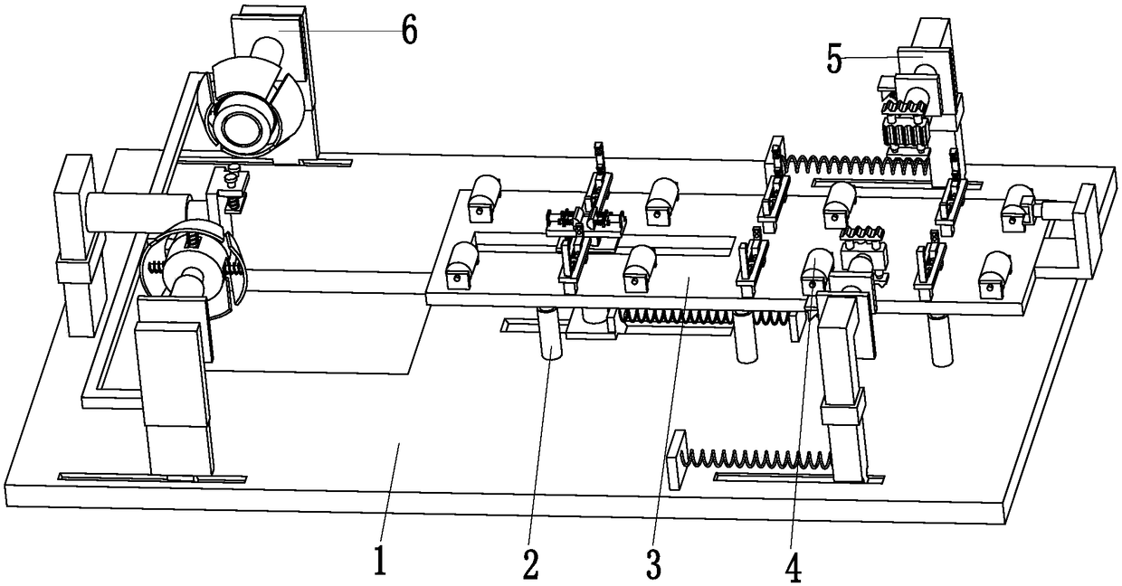
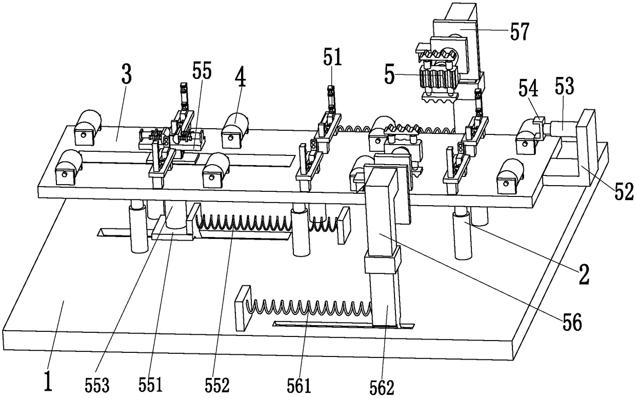
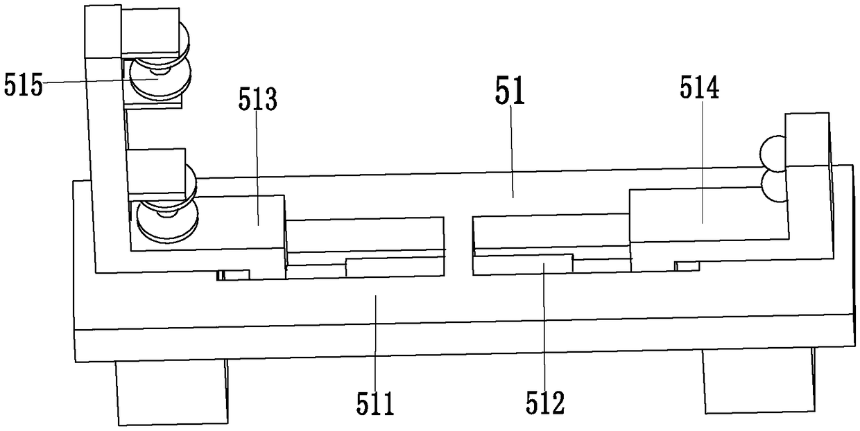
[0039] Such as Figure 1 to Figure 8 As shown, a steel structure correction and lifting system includes a support base plate 1, a support push rod 2, a placement plate 3, a rotating roller 4, a position adjustment device 5 and a positioning device 6. The middle part of the support base plate 1 is provided with a lifting slide A positioning chute is pr...


PUM


Abstract

The invention relates to a steel structure correcting and lifting system and a construction technology thereof. The steel structure correcting and lifting system comprises a supporting base plate, supporting push rods, a placing plate, rotary rollers, a position adjusting device and a positioning device. The supporting push rods are uniformly mounted on the top of the right side of the supportingbase plate, the placing plate is installed on the tops of the supporting push rods, a square groove is formed in the middle of the right end of the placing plate, and rotary rollers are symmetricallymounted at the front and rear ends of the top of the placing plate. The position adjusting device is mounted on the top of the right side of the supporting base plate, and the positioning device is mounted on the top of the left side of the supporting base plate. The steel structure correcting and lifting system can solves the problems that when an existing steel structure stair is mounted, stairplacing angles need to be corrected manually, the manual moving of a steel structure stair is more difficult, the steel structure stair is lifted with human assistance, the stair cannot be fixed whenlifting the steel structure, a stair lifting angle cannot be controlled automatically, and wounding hidden danger happens when the stair is lifted.

Description

technical field [0001] The invention relates to the technical field of steel structures, in particular to a steel structure correction and lifting system and construction technology thereof. Background technique [0002] Due to the rise of apartment-style houses, high-ceilinged houses are particularly popular, especially young people now love to raise the house type. When decorating apartments, there are also different options for indoor stairs, such as rotating and turning stairs. , the most common existing stairs are straight up and down stairs, which are welded by steel structures. The existing common steel structure stairs are such as Figure 9 As shown, the main body of the staircase is two channel steel as the supporting steel frame, and the angle steel is welded in the channel steel as the pedal support of the staircase. [0003] The installation of steel structure stairs is mainly carried out manually. First, the welded steel structure stairs are manually placed on t...

Claims


Application Information

Patent Timeline
Patent Type & Authority Applications(China)
IPC IPC(8): E04F11/02E04G21/16E04G21/18
CPCE04F11/02E04G21/16E04G21/18E04G21/1841
Inventor 潘春燕
Owner 鹤山市建筑设计院有限公司
Why Eureka
Try Eureka