Incident-angle-based laser point cloud reflection intensity correction method

A laser point cloud and incident angle technology, which is applied in image enhancement, 3D image processing, image data processing, etc., can solve problems such as texture seams, image and point cloud registration errors, and achieve improved efficiency, high precision, Realize the effect of automation

Inactive Publication Date: 2018-11-16
陈年康
View PDF2 Cites 7 Cited by
  • Summary
  • Abstract
  • Description
  • Claims
  • Application Information

AI Technical Summary

Problems solved by technology

Due to image distortion, point selection error, difference between point cloud and image resolution, and registration error between image and point cloud, it can only satisfy the seamless phenomenon of texture mapping between two adjacent images for point cloud, but cannot satisfy adjacent The texture mapping of the two images to the model will inevitably cause texture seams

Method used


Image

  • Incident-angle-based laser point cloud reflection intensity correction method
  • Incident-angle-based laser point cloud reflection intensity correction method
  • Incident-angle-based laser point cloud reflection intensity correction method

Examples


Embodiment Construction

[0050] The present invention will be further described in detail below in conjunction with the accompanying drawings, so that those skilled in the art can implement it with reference to the description.

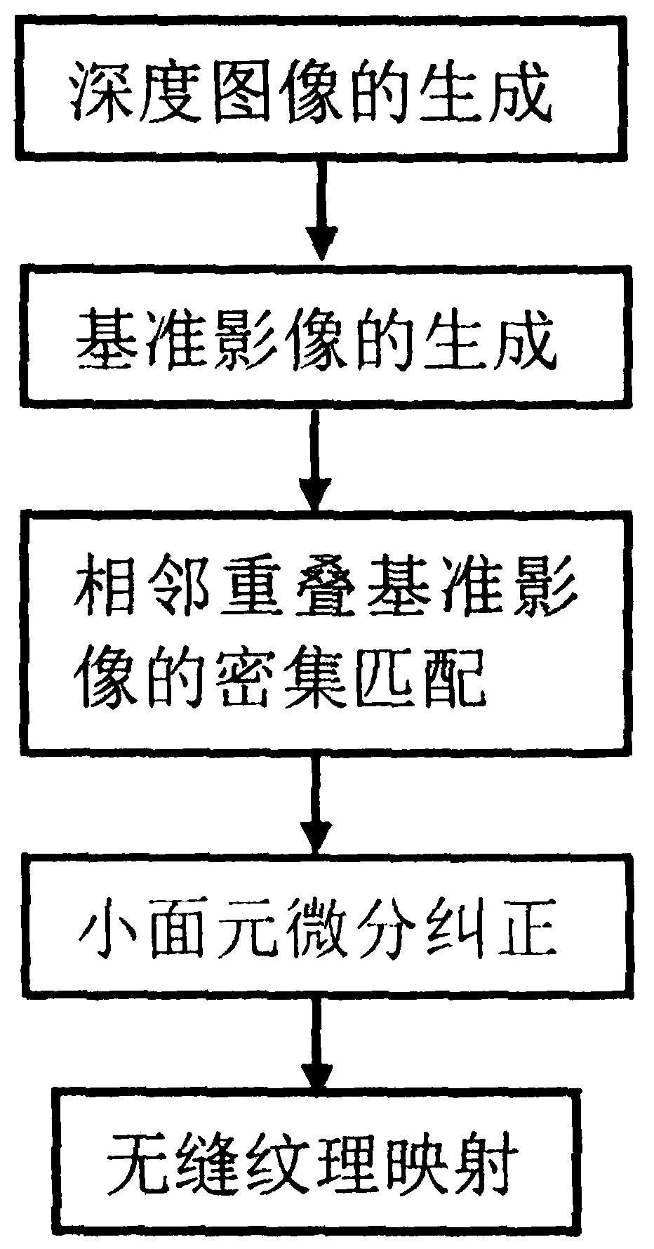
[0051] like figure 1 As shown, the present invention provides a seamless texture mapping method of laser point cloud and image based on plane reference plane interpolation, comprising the following steps:

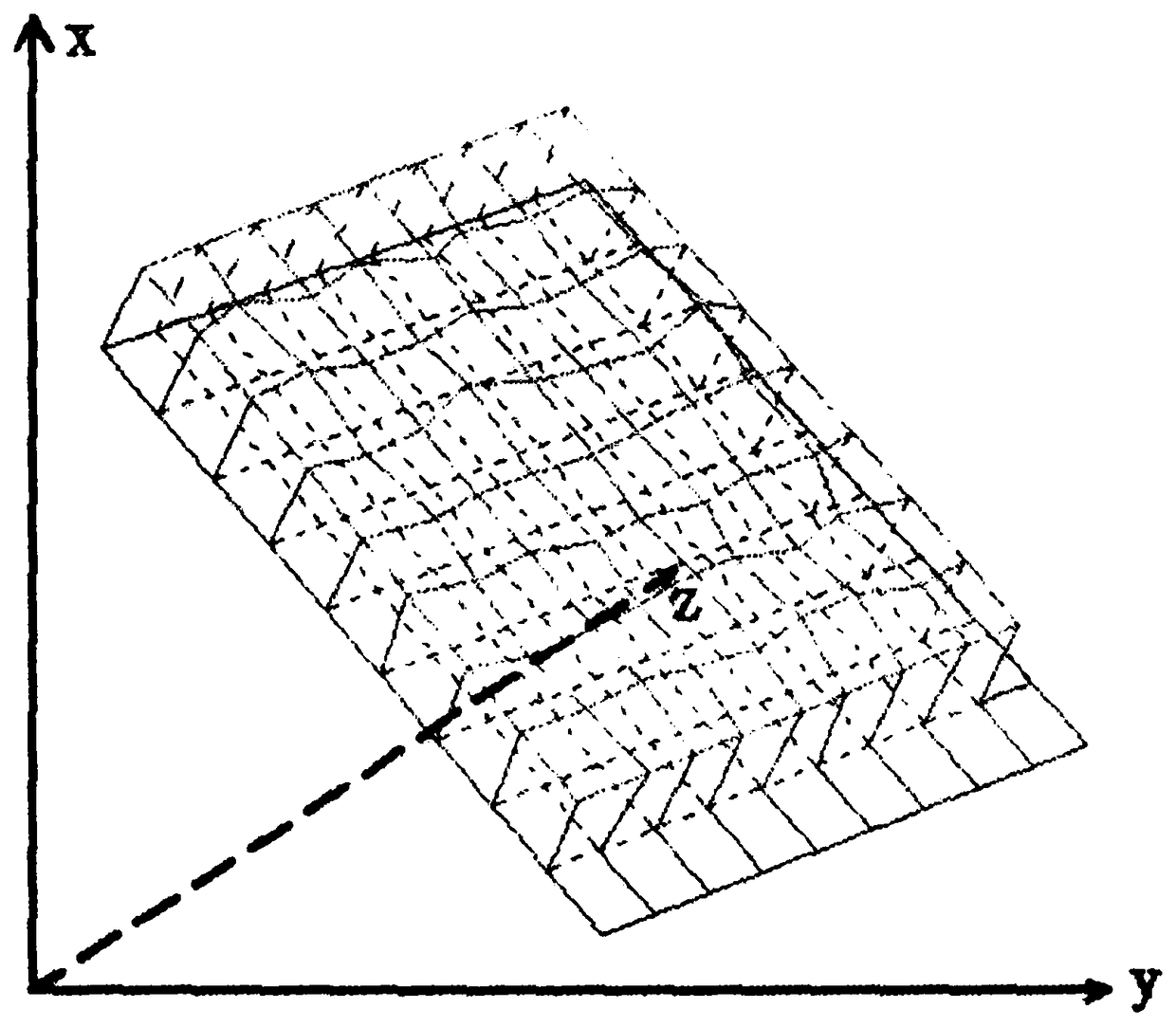
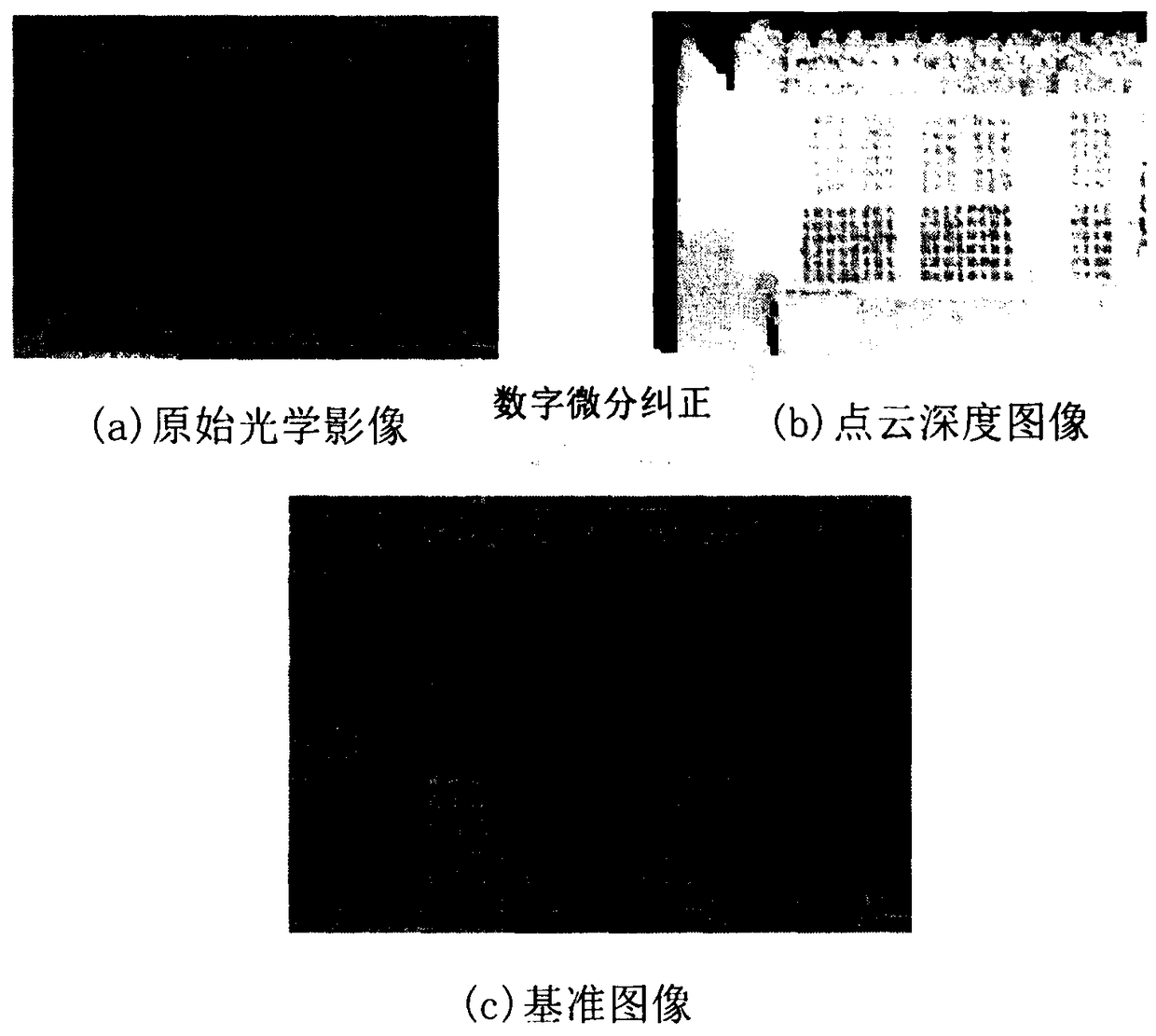
[0052] Step 1. Depth image generation: According to the fitting plane reference plane of the point cloud, and through the interpolation of a certain grid, a depth image is generated.

[0053] A depth image is a type of image. Each pixel stores the distance from a three-dimensional point in space to a reference plane. The image has a spatial position and attitude, and is stored in a two-dimensional lattice. Through the calculation of corresponding parameters, a three-dimensional model can be expressed. According to the shape of the object, the depth image reference plane ...


PUM


Abstract

The invention discloses an incident-angle-based laser point cloud reflection intensity correction method. The method comprises: step one, generating a depth image by interpolation of a certain grid according to a fitting plane reference plane; step two, with a digital differential correction technique, generating a reference plane image by using registration parameters, depth image models and thecollinear equations of the image and the point cloud; step three, carrying out rough matching by using SIFT matching, and carrying out dense matching on dense feature points extracted by a uniform grid by using a rough matching result as a constraint condition and other constraint conditions; step four, establishing a triangulation network by using a dense matching result, correcting an overlappedreference image based on radiation transformation parameters, and generating a corrected image by using an interpolating RGB method; and step five, according to a relationship between a depth image model and the reference image, generating a seamless color model for the corrected reference image by using a texture mapping technique.

Description

technical field [0001] The invention relates to the field of three-dimensional texture reconstruction of ground laser radar data. In particular, it relates to an automatic seamless texture reconstruction method for ground lidar and texture image data. LiDAR obtains point cloud data by scanning objects, uses point cloud data to build a 3D model, and completes 3D geometric reconstruction. The scanned object is photographed to obtain its texture image, and the texture is mapped to the 3D model through the registration of the point cloud and the image, and a color 3D model is generated to complete the texture modeling. Background technique [0002] Ground lidar technology, also known as real scene reproduction technology, has developed rapidly in the past ten years. It can quickly and large-scale acquisition of 3D point cloud models of scanned objects, and has been widely used in cultural heritage protection and large steel structures. Building quality inspection and deformati...

Claims


Application Information

Patent Timeline
Patent Type & Authority Applications(China)
IPC IPC(8): G06T15/04G06T5/00
CPCG06T5/00G06T15/04G06T2207/10044
Inventor 陈年康
Owner 陈年康
Why Eureka
Try Eureka