Small cycle permanent magnet type staggered undulator magnetic circuit

An undulator and small cycle technology, applied in the field of undulators, can solve the problems of high cost and maintenance costs, difficulty, and unstable performance, and achieve the effects of low manufacturing and operating costs, avoiding low temperature conditions, and stable performance.

Active Publication Date: 2018-11-16
INST OF APPLIED ELECTRONICS CHINA ACAD OF ENG PHYSICS
View PDF6 Cites 1 Cited by
  • Summary
  • Abstract
  • Description
  • Claims
  • Application Information

AI Technical Summary

Problems solved by technology

Vacuum undulators have been used in SACLA and SwissFEL devices. The minimum period of this type of undulator reported is 15mm. This result is close to the limit, and it is difficult to further reduce it.
Although the period of superconducting undulators and low-temperature undulators can be reduced to 10mm, the cost and maintenance costs are high, and the performance is not stable enough in large-scale use, and the low-temperature environment also consumes a lot of energy to maintain
The period of the microwave undulator can also be about 10mm, but it is still in the laboratory research stage, and the performance cannot meet the requirements of the XFEL device.

Method used


Image

  • Small cycle permanent magnet type staggered undulator magnetic circuit
  • Small cycle permanent magnet type staggered undulator magnetic circuit
  • Small cycle permanent magnet type staggered undulator magnetic circuit

Examples


Embodiment 1

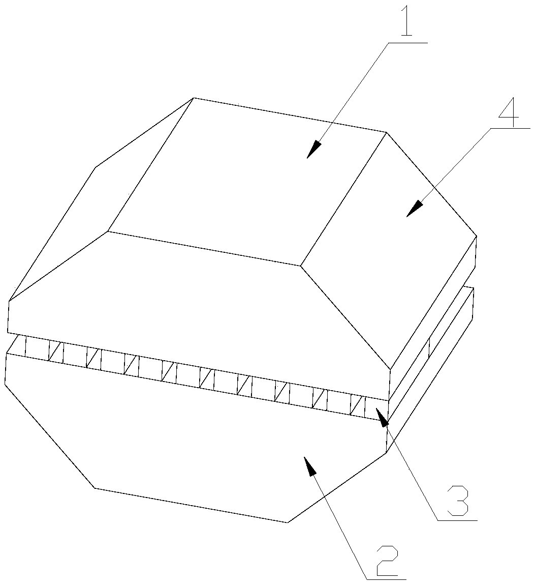
[0023] Such as figure 1 and figure 2 As shown, a small-period permanent magnet type staggered undulator magnetic circuit includes two permanent magnets facing each other with a certain gap. The permanent magnets are NdFeB permanent magnets, samarium cobalt permanent magnets or ferrite permanent magnets. The permanent magnet can be made of a whole permanent magnet block as required, or it can be formed by bonding several small permanent magnet blocks. In this embodiment, the two permanent magnets are respectively the first permanent magnet 1 and the second permanent magnet 2 , the magnetization directions of the first permanent magnet 1 and the second permanent magnet 2 are the same and are all along the longitudinal direction, and a longitudinal magnetic field in the opposite direction is generated in the gap between the first permanent magnet 1 and the second permanent magnet 2, and the first permanent magnet The two ends of the magnet 1 and the second permanent magnet 2 ar...

Embodiment 2

[0026] The same part of this embodiment and Embodiment 1 will not be described again, the difference is:

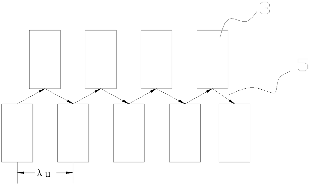
[0027] Such as Figure 4 As shown, in this embodiment, the cross-section of the soft iron pole 3 is U-shaped, and the flow direction of the magnetic flux of the transverse component is as follows image 3 indicated by the arrow.


PUM


Abstract

The invention relates to a small cycle permanent magnet type staggered undulator magnetic circuit and belongs to the technical field of undulators. The small cycle permanent magnet type staggered undulator magnetic circuit includes two permanent magnets arranged opposite to each other with a certain gap, two rows of soft iron magnetic poles disposed at intervals periodically are disposed in the gap of the two permanent magnets, a magnetic gap is formed between the two rows of soft iron magnetic poles, and each soft iron magnetic pole is staggered by the opposite soft iron magnetic pole by halfa cycle. The longitudinal magnetic flux generated between the two permanent magnets is bent by the soft iron magnetic poles, so that a cycle undulation magnetic field is generated in the horizontal direction, and the small cycle permanent magnet type staggered undulator magnetic circuit has the advantages of being stable in performance and low in manufacturing and operation cost.

Description

technical field [0001] The invention relates to the technical field of undulators, in particular to a small-period permanent magnet type staggered undulator magnetic circuit. Background technique [0002] X-ray free-electron laser (XFEL) is an important platform for contemporary scientific research, but it also has problems such as huge scale and high cost. Therefore, building a compact XFEL has become an important research direction, and reducing the period of the undulator is one of the feasible ways . [0003] In order to obtain undulators with small period and high field strength, superconducting undulators, vacuum undulators, cryogenic undulators and microwave undulators have been successively developed. Vacuum undulators have been applied to SACLA and SwissFEL devices. The minimum period of this type of undulator reported so far is 15mm. This result is already close to the limit and it is difficult to further reduce it. Although the period of superconducting undulato...

Claims


Application Information

Patent Timeline
Patent Type & Authority Applications(China)
IPC IPC(8): H01F7/02
CPCH01F7/0273
Inventor 闫陇刚邓德荣李鹏周奎吴岱单李军王建新肖德鑫刘宇
Owner INST OF APPLIED ELECTRONICS CHINA ACAD OF ENG PHYSICS
Why Eureka
Try Eureka