Automatic processing equipment for metal tubes

A technology for processing equipment and metal pipes, which is applied in the field of automatic processing equipment for metal pipes, can solve problems such as low turning production efficiency, achieve the effects of improving production efficiency, realizing automatic loading and unloading production, and ensuring accurate matching

Inactive Publication Date: 2018-11-20
长兴新亚环保机械科技股份有限公司
View PDF0 Cites 4 Cited by
  • Summary
  • Abstract
  • Description
  • Claims
  • Application Information

AI Technical Summary

Problems solved by technology

[0005] The purpose of the present invention is to address the deficiencies of the prior art and provide an automatic processing equipment for metal pipes. During the process of directional transfer of the steel pipe by the push assembly, the clamp can tighten the workpiece and contact the power assembly through the jacking part to realize the workpiece. Rotation, solving the technical problem of low turning production efficiency existing in the prior art

Method used


Image

  • Automatic processing equipment for metal tubes
  • Automatic processing equipment for metal tubes
  • Automatic processing equipment for metal tubes

Examples


Embodiment 1

[0036] Embodiments of the present invention are described in detail below, examples of which are shown in the drawings, wherein the same or similar reference numerals designate the same or similar elements or elements having the same or similar functions throughout. The embodiments described below by referring to the figures are exemplary and are intended to explain the present invention and should not be construed as limiting the present invention.

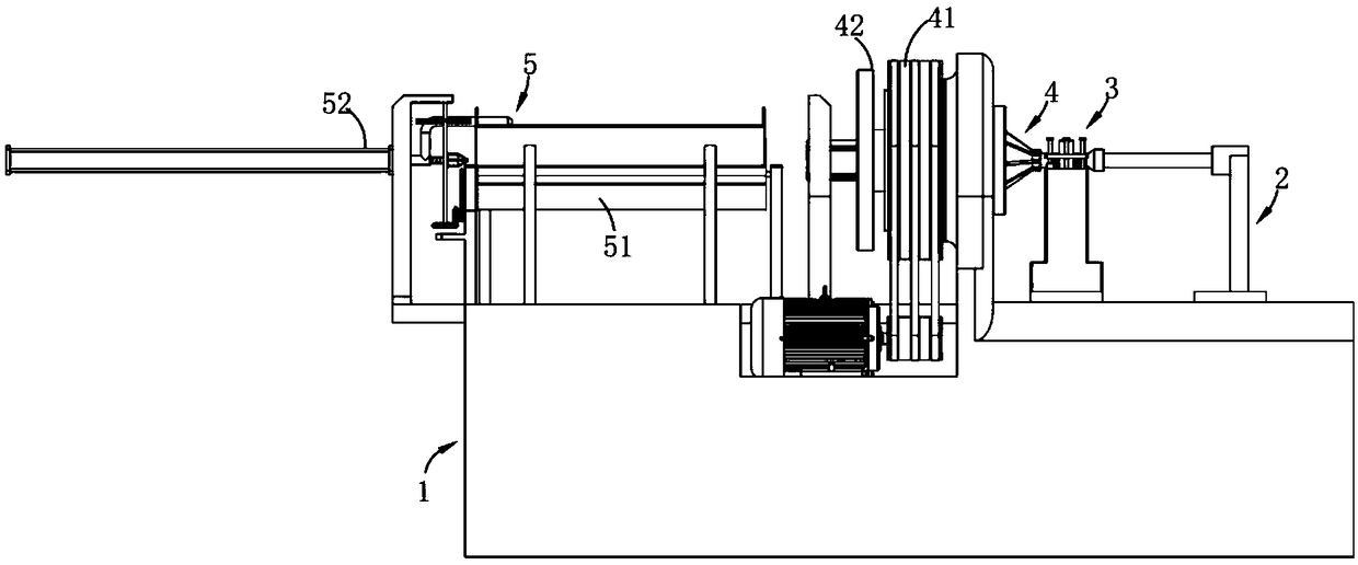
[0037] Such as figure 1 , 2 As shown in , 3, 4 and 5, a metal pipe automatic processing equipment includes a bed 1, a top cone 2 and a turning mechanism 3, and also includes:

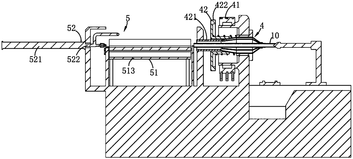
[0038] The clamping mechanism 4, the clamping mechanism 4 includes a power assembly 41 arranged on the bed 1 and a clamping assembly 42 that drives the workpiece 10 to rotate, the clamping assembly 42 includes a power assembly 41 arranged in the power assembly 41 and The rotating jacket 421 and the pretensioning part 422 that squeezes the jacket 421 to t...

Embodiment 2

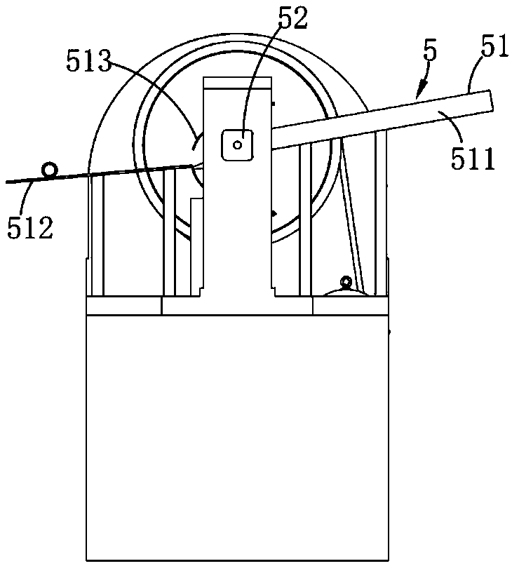
[0044] Such as figure 1 , 2 As shown in and 8, the same or corresponding parts as in the first embodiment adopt the corresponding reference numerals of the first embodiment. For the sake of simplicity, only the differences from the first embodiment are described below; The difference is that the push assembly 52 is fixedly arranged on the bed 1 and is located at one end of the transfer assembly 513, which includes a fixed cylinder 521, a reciprocating moving rod 522 driven by the cylinder 521, and a The end of the moving rod 522 is a positioning part 523 for positioning and tightening the workpiece 10 in the transfer assembly 513 , and a clutch fixed on the moving rod 522 to push the connection between the transmission plate 4222 and the power assembly 41 part 524 and the control part 525 that drives the transfer assembly 513 to rotate in the process of moving through the clutch part 524; The clutch part 524 pushes the turntable 4222 into contact with the power assembly 41 t...


PUM


Abstract

The invention relates to the technical field of tube processing and production, in particular to automatic processing equipment for metal tubes. The automatic processing equipment comprises a lathe bed, a tip cone, a turning mechanism and a clamping mechanism, wherein the clamping mechanism comprises a power assembly, a clamping assembly comprises a jacket which is rotatably arranged in the powerassembly and a pretightening part which is used for extruding the jacket so as to press a workpiece located in the jacket, and the pretightening part makes intermittent contact with the power assemblyso as to synchronously drive the workpiece to rotate to be turned by the turning mechanism; a feed mechanism comprises a feed part which communicates with the jacket and a push assembly which is located on one end of the feed part so as to transfer the workpiece located in the feed part into the jacket in a reciprocating mode, and the pretightening part is driven to make intermittent contact withthe power assembly by the push assembly. In the process that a steel tube is directionally transferred by the push assembly, the workpiece is pressed by a fixture, and a jacking part makes contact with the power assembly, so that the workpiece rotates, and the technical problem of low turning production efficiency in the prior art is solved.

Description

technical field [0001] The invention relates to the technical field of pipe processing and production, in particular to an automatic processing equipment for metal pipes. Background technique [0002] At present, steel pipe processing is widely used in all walks of life, and for the end processing of steel pipes, it is mostly realized by manual or semi-automatic clamping, especially for the processing and production of steel pipe ends with a certain length; and through manual clamping and unloading While its production efficiency is low, the production cost is high, which seriously affects the production efficiency of enterprises. [0003] China Patent No. 2015208970006 discloses an automatic upper and lower device for a CNC lathe, including a feeder, a feed conveyor belt device, a feed redirection slideway, a feed cylinder, a feed station, a grabbing manipulator, and a discharge slide Road, discharge conveyor belt device and oil pool, the feed end of the feed conveyor belt...

Claims


Application Information

Patent Timeline
Patent Type & Authority Applications(China)
IPC IPC(8): B23B5/08B23B23/04B23B15/00
CPCB23B5/08B23B23/04B23B2215/72B23B2270/08B23Q7/003
Inventor 梅丙林尹勇李威
Owner 长兴新亚环保机械科技股份有限公司
Why Eureka
Try Eureka