Full-automatic curve bending machining equipment
A kind of processing equipment, fully automatic technology, applied in the direction of metal processing equipment, shearing machine equipment, other manufacturing equipment/tools, etc., can solve the problem of inability to achieve fast and accurate curve bending, prone to accidents and mistakes, and low efficiency of manual processing and other problems, to achieve the effect of fixed stability, convenient control and convenient maintenance
- Summary
- Abstract
- Description
- Claims
- Application Information
AI Technical Summary
Problems solved by technology
Method used
Image
Examples
Embodiment 1
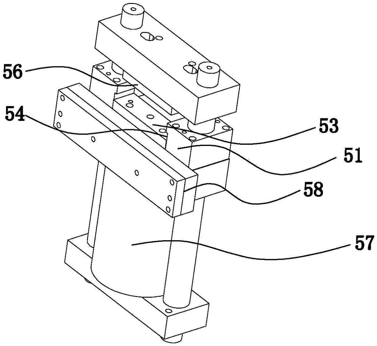
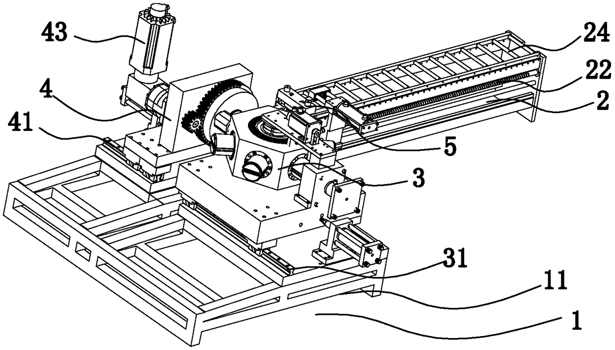
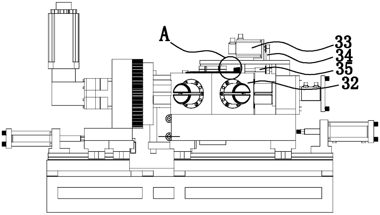
[0060] Refer to attached Figure 1-13 As shown, the fully automatic curve bending processing equipment includes a main body 1, and the main body 1 includes a frame 11. The main body 1 is provided with a feeding assembly 2, a folding arm chuck tower assembly 3, a universal folding head assembly 4, and a shearing assembly. The cutting assembly 5, the collecting and conveying bin mechanism and the control assembly 6, the folding arm chuck tower assembly 3 and the universal folding head assembly 4 are all located on the frame 11.
[0061] Feeding assembly 2 is cuboid structure, is provided with pulley 24 on the top, and pulley 24 forms pulley conveyor belt, clamping pincer 21 is positioned at the top of pulley 24, and first transmission mechanism 22 is positioned at feed assembly, and with feed assembly It is a sliding arrangement, which is specifically the transmission realized by the screw slider mechanism (the servo motor drives the slider to slide, and the slider and the clamp...
Embodiment 2
[0072] Refer to attached Figure 14 As shown, the difference between Embodiment 2 and Embodiment 1 is that: the folding arm chuck tower assembly 3 includes a folding arm chuck 38, which is only driven by the third transmission mechanism 31 and cannot be rotated. , which reduces production costs and enables small-scale enterprises to purchase.
Embodiment 3
[0074] Refer to attached Figure 15-16 As shown, the difference between Embodiment 3 and Embodiment 1 is that: the folding arm chuck tower assembly 3 and the universal folding head assembly 4 are located at the end of the feeding assembly, and the folding arm chuck tower assembly 4 is located at the universal Above or below the folding head assembly 5, the metal raw material 7 is vertically fixed by feeding clamps, the metal raw material 7 is fixed vertically through the folding arm chuck 38 and passes through the folding arm chuck 38, and the protruding part of the metal raw material 7 is located at the ten thousand On the movement track of the folding head 47, the curved bending is realized by rotating the universal folding head 47. Both the folding arm chuck tower assembly 3 and the universal folding head assembly 4 are arranged to rotate independently of each other.
PUM
 Abstract
Description
Claims
Application Information
 - R&D
- Intellectual Property
- Life Sciences
- Materials
- Tech Scout
- Unparalleled Data Quality
- Higher Quality Content
- 60% Fewer Hallucinations
Browse by: Latest US Patents, China's latest patents, Technical Efficacy Thesaurus, Application Domain, Technology Topic, Popular Technical Reports.
© 2025 PatSnap. All rights reserved.Legal|Privacy policy|Modern Slavery Act Transparency Statement|Sitemap|About US| Contact US: help@patsnap.com


