Six-freedom-degree manipulator

A technology of manipulators and degrees of freedom, applied in the direction of manipulators, program-controlled manipulators, manufacturing tools, etc., can solve the problems of increasing the inertia of the cantilever, reducing the stability of the manipulator, and increasing the load of the lower joints, so as to reduce the inertia of the cantilever and improve the motion accuracy and running stability, reducing the effect of lower joint load

Inactive Publication Date: 2018-11-20
SHANGHAI UNIV
View PDF8 Cites 8 Cited by
  • Summary
  • Abstract
  • Description
  • Claims
  • Application Information

AI Technical Summary

Problems solved by technology

[0003] In the existing traditional manipulator structure, the motors are installed at the joints. Although this structure is simple and compact, when it is applied to a multi-joint manipulator, the weight of the motor itself becomes part of the self-weight of the cantilever, causing the load on the lower joints to rise sharply. At the same time, the inertia of the cantilever is increased, which reduces the running stability
The invention with the publication number CN105215986A disclosed a multi-axis manipulator on January 6, 2016, which uses a high-quality servo motor to cooperate with the transmission structure of the RV series reducer dedicated to the robot. However, the multi-axis manipulator is also as mentioned above. The motors are all installed at the joints, which can easily increase the load on the lower joints, increase the inertia of the cantilever, and reduce the running stability. The invention with the publication number CN104589333A disclosed a five-degree-of-freedom mechanical arm on May 6, 2015 , driven by four DC servo motors, but the motors are all installed at the joints. The invention with the publication number CN104589333A disclosed a mechanical arm on March 30, 2016, which drives the first drive device for the first joint structure to move and Although the second driving device that drives the movement of the second joint structure is set in the housing cavity of the arm body, the driving motors are also installed at the joints, which reduces the stability of the mechanical arm.

Method used


Image

  • Six-freedom-degree manipulator
  • Six-freedom-degree manipulator
  • Six-freedom-degree manipulator

Examples


Embodiment Construction

[0024] In order to make the objectives, technical solutions, and advantages of the embodiments of the present invention clearer, the following will clearly describe the technical solutions in the embodiments of the present invention with reference to the accompanying drawings in the embodiments of the present invention. Obviously, the described embodiments are the present invention. Invented some embodiments, but not all embodiments. Based on the embodiments of the present invention, all other embodiments obtained by those of ordinary skill in the art without creative work shall fall within the protection scope of the present invention.

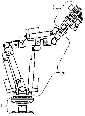
[0025] The embodiment of the invention discloses a six-degree-of-freedom mechanical arm, such as figure 1 As shown, the mechanical arm includes: a base part 1, a middle arm part of a large arm 2, and a wrist part 3. The rotating shaft flange 1-7 of the base part 1 and the disc 2-20 of the boom middle arm part 2 are connected by thrust roller bea...


PUM


Abstract

The invention discloses a six-freedom-degree manipulator. The six-freedom-degree manipulator is composed of a base part, a large and medium arm part, and a wrist part, wherein, the base part is rotatably connected with the large and medium arm part through a thrust roller bearing, and the large and medium arm part is connected with the wrist part through bolts; the rotation relationship between large and medium arms and a base is the first degree of freedom, the rotation relationship between the large arm and a round disc is the second degree of freedom, the rotation relationship between the medium arm and the large arm is the third degree of freedom, and the rotation relationship between the wrist and the medium arm is the fourth degree of freedom; and the rotation relationship between amotor connecting piece and a motor upper bracket is the fifth degree of freedom, and the rotation relationship between a tail end flange and a bevel gear connecting piece is the sixth degree of freedom. The large and medium arms are each of a hollow carbon fiber structure, in the case of ensuring the strength, the weight is greatly reduced, an encoder is mounted on a joint shaft, the closed-loop control is conducted so as to ensure the accuracy of motion, and the manipulator has the characteristics that the lower joint load can be reduced, the cantilever inertia is reduced, and the operationalstability is improved.

Description

Technical field [0001] The invention relates to an industrial automation equipment, and more specifically, to a six-degree-of-freedom mechanical arm. Background technique [0002] Manipulator is a kind of industrial robot. It is composed of manipulator, controller, servo drive system and detection sensor device. It is a kind of human-like operation, automatic control, repeatable programming, and can complete a variety of tasks in three-dimensional space. Automated production equipment. Robotic arms can greatly improve production efficiency, stabilize and improve product quality, improve workers’ working conditions, and increase the degree of mechanization and automation of industrial production. In exceptional temperature, high pressure, dust, high noise, and radioactive and polluted occasions, robotic arms It can play a great effect. [0003] In the existing traditional manipulator structure, the motors are installed at the joints. Although this structure is simple and compact, ...

Claims


Application Information

Patent Timeline
Patent Type & Authority Applications(China)
IPC IPC(8): B25J9/12B25J9/16B25J9/00
CPCB25J9/0009B25J9/12B25J9/16B25J9/1628
Inventor 解杨敏季力黄敏健周锐史航
Owner SHANGHAI UNIV
Why Eureka
Try Eureka