
Unmanned flying machine for surveying and mapping

An unmanned aerial vehicle and a surveying and mapping camera technology, applied in the field of unmanned aerial vehicles for surveying and mapping, can solve the problems of the camera of the surveying and mapping unmanned aerial vehicle being photographed or blurred, affecting the effect of aerial photography operations, and the inability of parts to be used universally, so as to improve the clarity of photographing. degree and effect, easy installation, and the effect of isolating airflow interference

Inactive Publication Date: 2018-11-20
智飞智能装备科技东台有限公司
View PDF8 Cites 1 Cited by
  • Summary
  • Abstract
  • Description
  • Claims
  • Application Information

AI Technical Summary

Problems solved by technology

[0004] 1) In the actual application of existing aircraft in field surveying and mapping, industrial inspection or outdoor photography, operators often need to carry more equipment, and the components cannot be used in common, and the burden on them is too heavy;
[0005] 2) The shooting operation of the surveying and mapping camera is easily disturbed by the external environment, especially when the camera is mounted on the surveying and mapping drone, and the vibration of the components of the surveying and mapping drone during the flight, as well as the vibration caused by the interference of the airflow The interference of the camera is more obvious, which will make the camera of the surveying and mapping UAV blurred or blurred, which will affect the effect of the aerial photography operation

Method used


Image

  • Unmanned flying machine for surveying and mapping
  • Unmanned flying machine for surveying and mapping
  • Unmanned flying machine for surveying and mapping

Examples


Embodiment

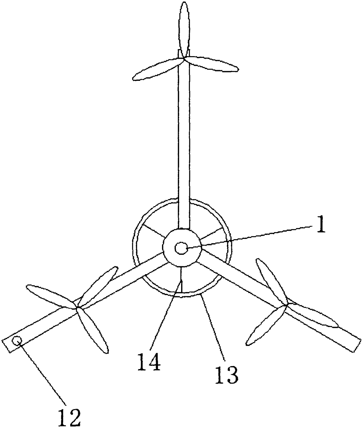
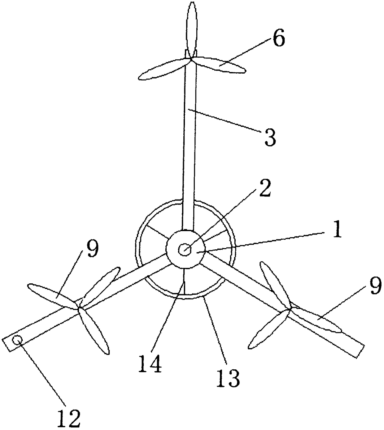
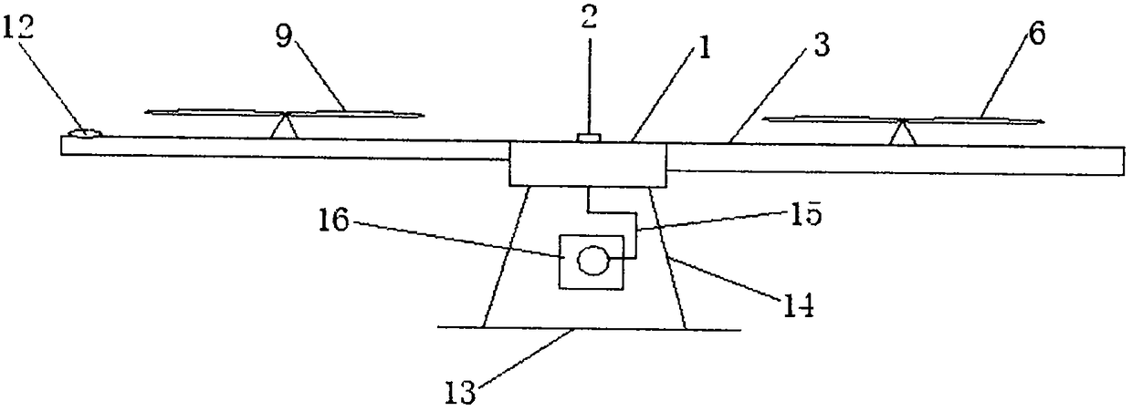
[0028] Example: such as Figure 1-5 As shown, the present invention provides a technical solution, an unmanned aerial vehicle for surveying and mapping, including three sets of support rods with an angle of 120 degrees between axes, a brushless DC motor and rotor, a central console 1, and a landing support 13 , a wireless transceiver module 12 and a hand-held control terminal, the three sets of support rods with an angle of 120 degrees between axes are connected to the central console 1, the DC motor and the rotor are arranged on the support rods, and the The central console 1 is uniformly controlled, and the lifting support 13 is connected with the central console 1 through a connection structure 14. A three-axis stabilized pan-tilt 15 is arranged below the central console 1. On the top of the three-axis stabilized pan-tilt 15 The surveying and mapping camera 16 is connected through the shock absorber, and the shock absorber includes a shock-absorbing lower plate and a shock-...


PUM


Abstract

The invention discloses an unmanned flying machine for surveying and mapping. The unmanned flying machine comprises three groups of supporting rods having inter-axle included angles of 120 degrees, adirect-current motor and rotors, a central control board, a take-off and landing bracket, a wireless transceiver module and a handheld control terminal, wherein the three groups of supporting rods having inter-axle included angles of 120 degrees are connected with the central control board; the direct-current motor and rotors are arranged on the supporting rods; the take-off and landing bracket isconnected with the central control board by virtue of a connecting structure; a three-axis stable pan-tilt is arranged below the central control board; a mapping camera is connected onto the three-axis stable pan-tilt by virtue of a damper; the damper comprises a lower damping plate and an upper damping plate; the wireless transceiver module is arranged on the supporting rods. The unmanned flyingmachine disclosed by the invention can perform aerial working mapping, and can also serve as a tripod mapping platform on the ground. The mapping camera is connected by the damper, so that airflow interference and motor vibration in the flying process of the unmanned aerial vehicle body can be effectively isolated, and the shooting definition and effect of the mapping camera can be improved.

Description

technical field [0001] The invention relates to the technical field of unmanned aerial vehicles, in particular to an unmanned aerial vehicle for surveying and mapping. Background technique [0002] UAV aerial photography, surveying and detection technology can be widely used in resource exploration, environmental monitoring, land and water resource investigation, crop growth monitoring and yield estimation, agricultural operations, natural disaster monitoring and evaluation, urban planning and municipal management, forest pest protection and Monitoring, ecological environment protection and testing, public security, national defense, digital earth, advertising photography and other fields have broad market demand. At present, most unmanned rotorcrafts are of four-axis or six-axis structure, which has the advantages of easy control of flight attitude and simple structure. [0003] However, in the process of designing the unmanned surveying and mapping aircraft, the inventor ...

Claims


Application Information

Patent Timeline
Patent Type & Authority Applications(China)
IPC IPC(8): B64D47/08B64C27/08G03B17/56G03B30/00
CPCG03B17/56B64C27/08B64D47/08B64U2101/30B64U10/10
Inventor 朱银广涂强
Owner 智飞智能装备科技东台有限公司
Learn More