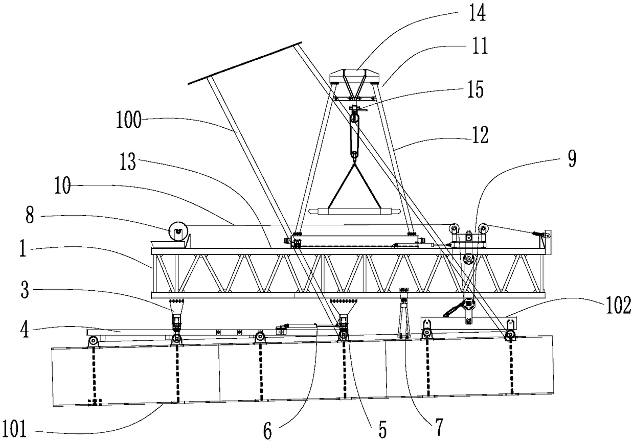
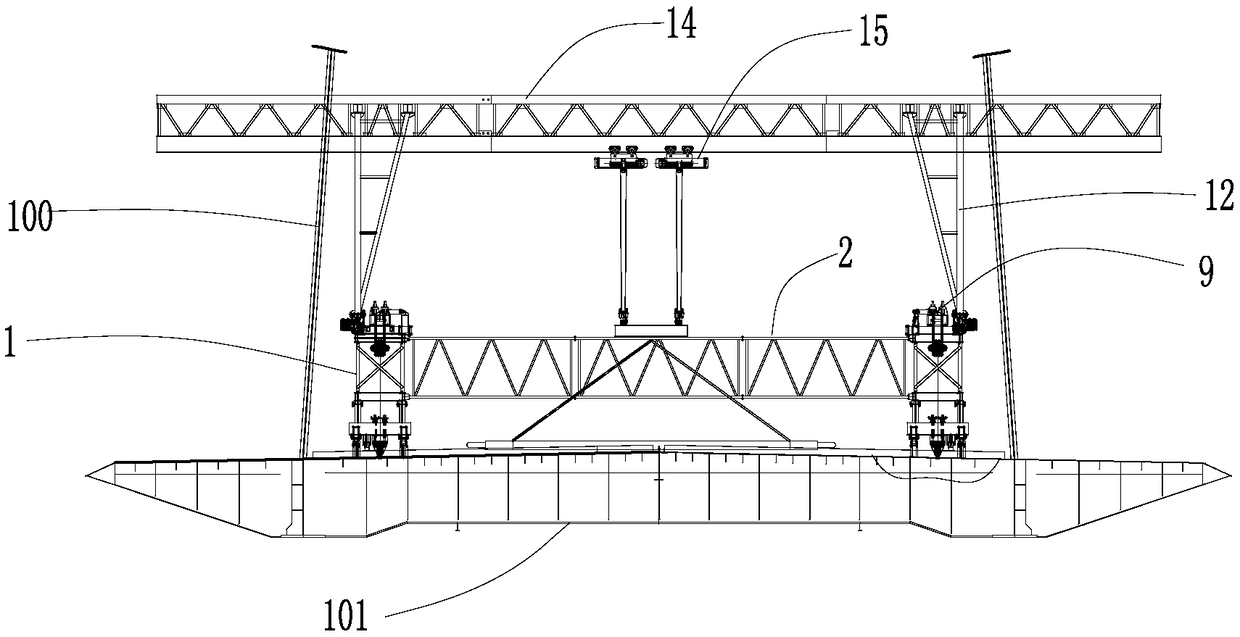
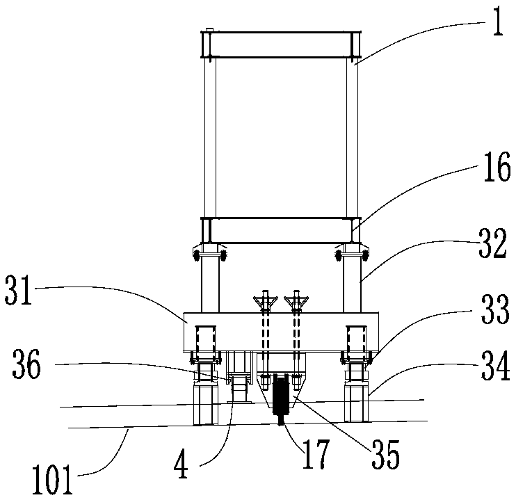
[0028] Such as figure 1 , figure 2 As shown, the present invention provides a cable-stayed bridge steel beam and bridge deck combined hoisting equipment, including a bridge deck crane for hoisting the steel beam, the bridge deck crane includes two horizontally arranged along the bridge The main girder 1 on the inner side of the stay cable 100 of the bridge, the front and rear ends of the two main girders 1 are respectively connected by a front crossbeam and a rear crossbeam 2. The main girder 1 and the front crossbeam and the rear crossbeam 2 are all truss structures. There are two upper chords and two lower chords; each main girder is provided with rear legs 3 at the bottom rear end. The upper end of the rear legs 3 and the lower chord of the main girder 1 are connected by bolts, and the lower ends of the rear legs are supported along the bridge. On the bridge deck crane slide rail 4 on the top surface of the steel beam 101, and anchored with the lifting lugs on the steel beam 101; each main beam is provided with a front leg 5 in the middle of the bottom of the main beam, and the upper end of the front leg 5 is connected to the main beam The lower chord of 1 is connected by bolts, and the lower end is supported on the slide rail 4 of the bridge deck crane. The lower end of the front leg 5 is also connected to a horizontally arranged jacking cylinder 6. One end of the jacking cylinder 6 is connected to the front leg 5. Connected by a pin, the other end is bolted to the bridge deck crane slide rail 4 through the connecting plate, and the anchoring end of the jacking cylinder 6 and the bridge deck crane slide rail is located between the front leg 5 and the rear leg 3 ; The bottom of each main beam is located between the front leg and the front end of the main beam with two auxiliary legs 7, the two auxiliary legs 7 are located on both sides of the main beam, and the two auxiliary legs are connected by a support shaft and supported by The shaft is supported at the bottom of the lower chord of the main girder, and the upper ends of the two auxiliary legs are connected by a limit screw located at the top of the lower chord of the main girder to lock the two auxiliary legs and the main girder. The lower ends of the two auxiliary legs are supported on steel The top surface of the beam; the rear end of the top surface of each main beam is provided with a hoist 8, and a spreader lifting system 9 is provided near the front end of the top surface of the main beam, and the spreader 102 is connected through the spreader lifting system 9. The hoisting system 9 is provided with a pulley block. The front end of the traction rope 10 of the hoist 8 bypasses the pulley block of the hoisting system and is fixedly connected to the front end of the main beam; the top of the bridge deck crane is provided with a gantry crane 11 for hoisting the bridge deck. The two ends of the gantry crane are respectively provided with two gantry crane legs 12, a gantry crane slide rail 13 is provided along the outer upper chord of the main beam of the bridge deck crane, and the lower end of the gantry crane leg is supported on the gantry crane slide rail on the main beam of the bridge deck crane 13, the upper end of the gantry crane leg is connected to the horizontally arranged bearing beam 14 of the transverse bridge. The two ends of the bearing beam 14 extend to the outside of the stay cable to form a cantilever. The bottom of the bearing beam is provided with a sliding beam, and the sliding beam is connected to There are two electric hoists 15 that can slide longitudinally along the sliding beam.
[0029] Such as image 3 As shown, the rear leg 3 includes a horizontally arranged rear leg cross brace 31, and the top ends of the rear leg cross brace 31 respectively pass through two rear leg connecting plates 32 and the two lower chords 16 of the main beam 1. Bolt connection, the bottom ends of the rear leg cross brace 31 are respectively provided with a vertical rear leg adjusting cylinder 33, the rear leg adjusting cylinder 33 is supported on the rear leg pad 34 on the top surface of the steel beam; the rear leg Two vertical anchoring plates 35 are arranged in the middle of the bottom of the cross brace 31. The lifting lugs 17 on the top surface of the steel beam are placed between the two anchoring plates 35, and the two anchoring plates 35 and the lifting lugs 17 are anchored by bolts; The bottom of the support 31 is located between a rear leg adjusting cylinder 31 and the anchor plate 35 with a rear leg slide groove 36, and the rear leg slide groove 36 is supported on the bridge deck crane slide rail 4.
[0030] Such as Figure 4 As shown, the front leg 5 includes a horizontally arranged front leg cross brace 51, and the top ends of the front leg cross brace 51 are respectively used by two front leg connecting plates 52 and the two lower chords 16 of the main beam 1. Bolt connection, a vertical front leg adjusting cylinder 53 is provided at the bottom ends of the front leg cross brace 51, and the front leg adjusting cylinder 53 is supported on the front leg pad 54 provided on the top surface of the steel beam; the front leg A front leg chute 55 is provided at the bottom of the cross brace 51 between the two front leg adjusting cylinders, and the front leg chute 55 is supported on the bridge deck crane slide rail 4.
[0031] Such as Figure 5 As shown, the lower end of the front leg 5 is also connected to a horizontally arranged jacking cylinder 6. One end of the jacking cylinder 6 is connected with the front leg 5 through a pin, and the other end is connected to the deck crane slide rail 4 through a connecting plate It is anchored by bolts, and the anchoring end of the jacking cylinder 6 and the slide rail of the deck crane is located between the front leg 5 and the rear leg 3.
[0032] Such as Image 6 As shown, the bottom of each main beam is located between the front leg and the front end of the main beam. Two auxiliary legs 7 are respectively located on both sides of the main beam 1. The two auxiliary legs 7 are connected by a support shaft 71 and supported by the support shaft. 71 is at the bottom of the lower chord 16 of the main beam 1, and the upper ends of the two auxiliary legs 7 are connected by a limit screw 72. The limit screw 72 is located at the top of the main beam lower chord 16 to lock the two auxiliary legs with the main beam. The lower end of the leg is supported on the top surface of the steel beam 101; the bottom of the auxiliary leg 7 is provided with a height adjustment bolt 73, the upper end of the height adjustment bolt 73 is screwed to the bottom of the auxiliary leg 7, and the lower end is supported on the top surface of the steel beam 101 .
[0033] Such as Figure 7 , Picture 8 As shown, the spreader lifting system 9 includes a base 91 set on the top of the main beam 1, a seat 92 is provided on the base 91, and a first fixed pulley 93 and a second fixed pulley are fixedly provided on the support 92. The fixed pulley 94 is provided with a movable pulley 95 under the main beam. The two fixed pulleys 93, 94 and the movable pulley 95 form the pulley block of the spreader lifting system. The traction rope 10 of the hoist sequentially bypasses the first fixed pulley 93 and the movable pulley 95. The second fixed pulley 94 is fixed to the front end of the main beam 1 of the bridge deck crane.
[0034] Such as Figure 7 As shown, the spreader lifting system 9 is provided with a spreader longitudinal adjustment cylinder 96; on the top surface of the main beam is provided a base slide rail 97 arranged along the bridge, and the bottom of the base is supported on the base slide rail At 97, one end of the spreader longitudinal adjustment cylinder 96 is connected to the rear end of the spreader base, and the other end is anchored to the base slide rail 97 in the bridge direction.
[0035] Such as Picture 8 As shown, the spreader lifting system 9 is provided with a spreader transverse adjustment cylinder 98, a support slide rail 99 arranged transversely on the top surface of the base 91, and the support 92 is supported on the support On the base slide rail 99, one end of the spreader transverse adjustment cylinder 98 is fixedly connected to the spreader support 92, and the other end is fixedly connected to one side of the base 91 in a transverse direction.
[0036] Such as Picture 9 As shown, the top of the bridge deck crane is provided with a gantry crane 11 for lifting the bridge deck. The gantry crane 11 adopts an existing ordinary cantilever gantry crane. Two gantry crane legs 12 are respectively provided at both ends of the gantry crane. A gantry crane slide rail 13 is provided along the outer upper chord of the main beam 1 of the bridge deck crane. The lower ends of the gantry crane legs support On the gantry crane slide rail 13 on the main beam of the bridge deck crane. The upper end of the gantry crane leg 12 is connected to a load beam 14 horizontally arranged across the bridge. Both ends of the load beam 14 extend to the outside of the stay cable to form a cantilever. The bottom of the load beam is provided with a sliding beam, and two sliding beams are connected An electric hoist 15 that can slide longitudinally along the sliding beam.
[0037] The above-mentioned cable-stayed bridge steel beam and bridge deck combination hoisting equipment is used to hoist the cable-stayed bridge steel beam and deck. The specific construction method is as follows:
[0038] (1) After the 0# steel beam of the cable-stayed bridge is hoisted, the 0# stay cable is installed and the second tension is completed, two slide rails for the movement of the bridge deck crane are laid on the 0# steel beam along the bridge direction , The two slide rails are respectively located on the inner side of the two stay cables, and the slide rails are adjusted to be horizontal;
[0039] (2) Assemble the cable-stayed bridge steel girder and bridge deck combined hoisting equipment on the 0# steel girder, and support the rear and front legs of the bridge deck crane on the slide rails; the lower ends of the auxiliary legs are supported on the steel The top surface of the beam, the upper end is temporarily locked with the main beam through the limit screw; the rear outrigger is anchored to the lifting lugs on the top surface of the steel beam; the gantry crane on the bridge deck crane is located between the rear outrigger and the front outrigger;
[0040] (3) Hoisting 1# steel beam: the gantry crane moves to a position 3800mm away from the front leg of the bridge deck crane on its centerline. The gantry crane centerline refers to the dividing line of the gantry crane along the longitudinal axis of the load beam; then the hoist is started Lower the spreader and lift the 1# steel beam section to the designed installation height, then lock the hoist;
[0041] (4) The gantry crane moves forward to 500mm away from the outriggers; butt the 1# steel beam with the 0# steel beam, install the 1# steel beam stay cable, and perform the first tension;
[0042] (5) Install the bridge deck on the 1# steel beam: the gantry crane continues to move forward between the front leg and the front end of the main beam, and the gantry crane is 1755mm away from the front leg; transport the bridge deck to the 1# beam by a beam truck , The middle bridge deck between the stay cables is hoisted by two electric hoists first; the outer bridge deck of the two stay cables is hoisted by a single electric hoist. When hoisting the outer bridge deck of the left stay cable, one electric hoist will move along The load-bearing beam moves to the right stay cable and hooks the main beam of the bridge deck crane below, the bridge deck is lifted by another electric hoist and moved to the outside of the left stay cable, and the bridge deck is installed to the designated position ; Then hoist the outer bridge deck of the right stay cable in the same way;
[0043] (6) After the bridge deck is installed, the gantry crane is moved 1255mm back to 500mm away from the front leg;
[0044] (7) Release the limit screw between the auxiliary leg and the main beam, manually push the auxiliary leg close to the front end of the main beam, and then temporarily lock it with the limit screw of the main beam;
[0045] (8) Release the anchorage between the rear outriggers and the main beam lifting lugs;
[0046] (9) Start the pushing cylinder of the front leg to push the main beam forward by 6m; during the forward movement of the main beam, the gantry crane on the upper part of the main beam moves backward synchronously;
[0047] (10) Lift the limit screw of the auxiliary leg and the main beam again, push the auxiliary leg forward 2m, and lock it with the limit screw of the main beam;
[0048] (11) Start the jacking cylinder of the front leg to push the main beam forward by 2m. During the movement of the main beam, the upper gantry crane moves backward synchronously;
[0049] (12) Through steps (9) to (11), the main beam moves forward into place; anchor the rear legs and the main beam lugs, perform the second tensioning of the stay cable on the 1# steel beam, and then hoist the next steel beam and steel The bridge deck on the girder is constructed in cycles according to steps (3) to (11) until all steel beams and bridge decks are hoisted.