Distribution type garbage treating device free of emission of low temperature pyrolysis gas

A low-temperature pyrolysis and treatment device technology, applied in lighting and heating equipment, combustion methods, combustion types, etc., can solve the problems of single treatment method, low resource recycling rate, and unrefined classification, and achieve enhanced preheating. Drying effect, high working efficiency, and the effect of reducing exhaust gas

Inactive Publication Date: 2018-11-20
HEILONGJIANG LANDE ULTRASONIC TECH CO LTD
View PDF0 Cites 2 Cited by
  • Summary
  • Abstract
  • Description
  • Claims
  • Application Information

AI Technical Summary

Problems solved by technology

At this stage, China mainly focuses on the treatment of waste that has been generated. The concept of controlling the source of waste generation similar to that of the United States has not been reflected in the technical route, and the treatment method is relatively simple, mainly the way of sanitary landfill. Due to the lack of detailed classification , leading to a very low recycling rate of resources

Method used


Image

  • Distribution type garbage treating device free of emission of low temperature pyrolysis gas
  • Distribution type garbage treating device free of emission of low temperature pyrolysis gas
  • Distribution type garbage treating device free of emission of low temperature pyrolysis gas

Examples


specific Embodiment approach 1

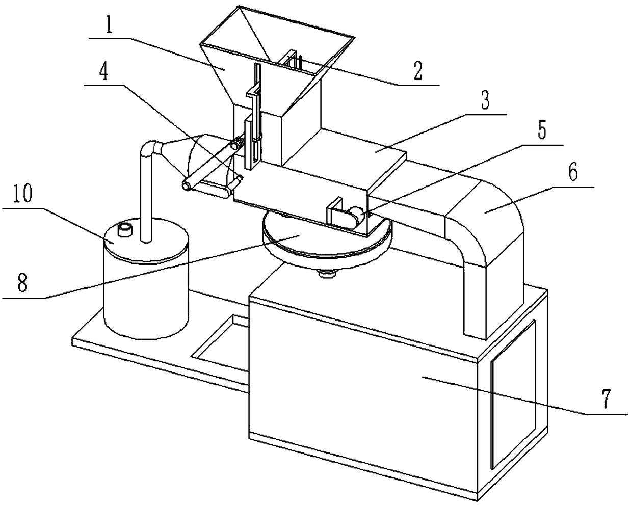
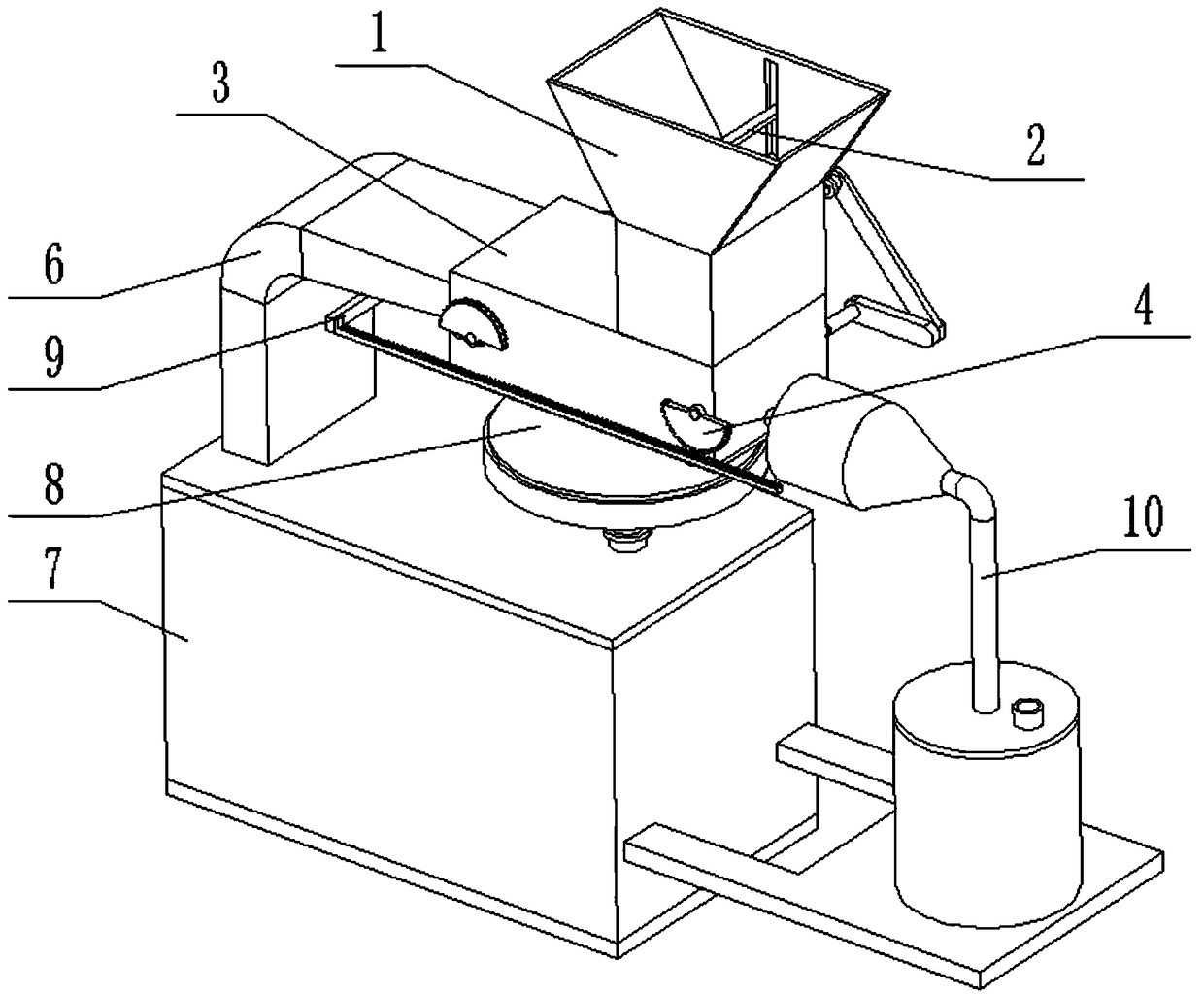
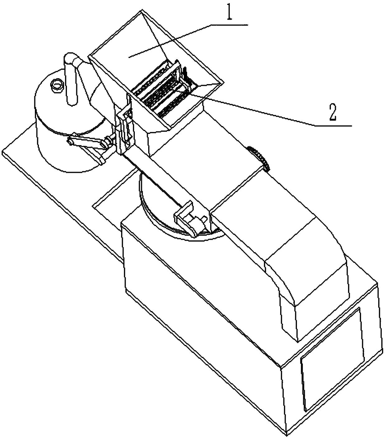
[0035] Such as Figure 1-14 As shown, the distributed garbage low-temperature pyrolysis gas emission-free treatment device includes a garbage drop box 1, a lifting garbage pressing mechanism 2, a garbage conveying preheating box 3, a garbage conveying mechanism 4, a driving motor 5, and a curved falling pipe 6. Low-temperature pyrolysis furnace 7, pyrolysis gas delivery mechanism 8, gas compression mechanism 9 and waste gas discharge treatment device 10, described garbage drop box 1 is fixedly connected and communicated with the upper end of garbage delivery preheating box 3; described garbage delivery preheating The right end of the box 3 is fixedly connected and communicated with the upper end of the curved falling pipeline 6, and the lower end of the curved falling pipeline 6 is fixedly connected and communicated with the low-temperature pyrolysis furnace 7; the low-temperature pyrolysis furnace 7 is fixedly connected and communicated with the pyrolysis gas delivery mechanis...

specific Embodiment approach 2

[0040] Such as Figure 1-14 As shown, the garbage conveying mechanism 4 includes a driving shaft 4-1, a driving roller 4-2, a driving gear 4-3, a driven gear 4-4, a gear shaft 4-5, a return half gear 4-6, a compression Half gear 4-7, driven shaft 4-8, driven roller 4-9, conveying belt 4-10, linkage shaft 4-11 and rotating connecting plate 4-12; both ends of the driving shaft 4-1 pass through The bearing with seat is rotatably connected to the rectangular box 3-1, and the front end of the driving shaft 4-1 is connected to the output shaft of the drive motor 5 through a coupling; the rear end of the driving shaft 4-1 is fixedly connected to the driving gear 4-3 , the driving gear 4-3 meshes with the driven gear 4-4, the driven gear 4-4 is fixedly connected to the gear shaft 4-5, and the gear shaft 4-5 is rotatably connected to the rectangular box body 3-1 through a bearing with seat; The return half gear 4-6 is fixedly connected to the gear shaft 4-5; the driving roller 4-2 is ...

specific Embodiment approach 3

[0042] Such as Figure 1-14 As shown, the gas compression mechanism 9 includes a linkage rack 9-1, a linkage plate 9-2, a push-pull rod 9-3 and a compression plate 9-4; the linkage rack 9-1 is fixedly connected to the linkage plate 9-2 One end of the linkage plate 9-2 is fixedly connected to one end of the push-pull rod 9-3, and the other end of the push-pull rod 9-3 is fixedly connected to the compression plate 9-4; the push-pull rod 9-3 is slidably connected to the On the right side of the combustion chamber 3-5; the compression plate 9-4 is connected with clearance fit to the inside of the combustion chamber 3-5; the linkage rack 9-1 is meshed with the compression half gear 4-7 or the return half gear 4 -6; when the compression half gear 4-7 is engaged with the linkage rack 9-1, the return half gear 4-6 is separated from the linkage rack 9-1; the return half gear 4-6 is engaged with the linkage gear When the bar 9-1 is used, the compression half gear 4-7 is separated from ...


PUM


Abstract

The invention relates to the field of garbage treatment and particularly relates to a distribution type garbage treating device free of emission of low temperature pyrolysis gas. The distribution typegarbage treating device comprises a garbage drop can, a lift type garbage pressing and falling mechanism, a garbage conveying and preheating box, a garbage conveying mechanism, a driving motor, a bent falling pipeline, a low-temperature pyrolyzing furnace, a pyrolysis gas conveying mechanism, a gas compressor and a waste gas emission treating device; the garbage drop can is fixedly connected andcommunicates with the upper end of the garbage conveying and preheating box; the right end of the garbage conveying and preheating box is fixedly connected and communicates with the upper end of the bent falling pipeline; and the lower end of the bent falling pipeline is fixedly connected and communicates with the low-temperature pyrolyzing furnace. The distribution type garbage treating device provided by the invention can be used for effectively carrying out pyrolysis treatment on the garbage and can also preheat and dry the to-be-treated garbage by utilizing combustible gas generated in pyrolysis of the garbage, and thus the pyrolysis efficiency and the pyrolysis effect of the garbage are improved.

Description

technical field [0001] The invention relates to the field of garbage treatment, in particular to a distributed garbage low-temperature pyrolysis gas emission-free treatment device. Background technique [0002] In the process of urbanization, garbage, as a product of urban metabolism, used to be a burden on urban development. Many cities in the world have been surrounded by garbage. Today, garbage is considered to be the most potential and inexhaustible "urban mine" and a "misplaced resource". This is not only an in-depth understanding of garbage, but also an inevitable requirement for urban development. [0003] At present, China's domestic waste treatment is mainly based on sanitary landfill, accounting for about 78% of the treatment volume, and the classification and subdivision of waste is not strong, and there is no more effective recycling route. my country's domestic waste treatment is at a relatively early stage, and there are many areas that need to be standardize...

Claims


Application Information

Patent Timeline
Patent Type & Authority Applications(China)
IPC IPC(8): F23G5/027F23G5/44
CPCF23G5/027F23G5/44
Inventor 张修全赵宪忠孙闯老延威张健
Owner HEILONGJIANG LANDE ULTRASONIC TECH CO LTD
Why Eureka
Try Eureka