
A controllable ultra-high flow rate and large flow water tunnel system and control method

A large flow, ultra-high-speed technology, applied in the field of experimental fluid mechanics, can solve the problems of reduced performance, poor reliability, and difficult implementation of water pump equipment, and achieve the effects of reducing power supply, reducing construction costs, and improving compression efficiency

Active Publication Date: 2020-05-19
XI AN JIAOTONG UNIV
View PDF5 Cites 0 Cited by
  • Summary
  • Abstract
  • Description
  • Claims
  • Application Information

AI Technical Summary

Problems solved by technology

Severe cavitation will greatly reduce the stability of the flow field in the water tunnel, thereby affecting the accuracy of related tests in the water tunnel; at the same time, excessive cavitation will cause the performance of water pumps and other related equipment to decrease
Existing water tunnel systems use water pumps as power devices to accelerate water. Due to the limitations of existing water pump technology, it is difficult to achieve high-flow and high-velocity equipment at the same time, and the efficiency of high-power water pump equipment is low. poor reliability

Method used


Image

  • A controllable ultra-high flow rate and large flow water tunnel system and control method
  • A controllable ultra-high flow rate and large flow water tunnel system and control method
  • A controllable ultra-high flow rate and large flow water tunnel system and control method

Examples


Embodiment Construction

[0040] The present invention will be further described in detail below in conjunction with specific embodiments, which are explanations of the present invention rather than limitations.

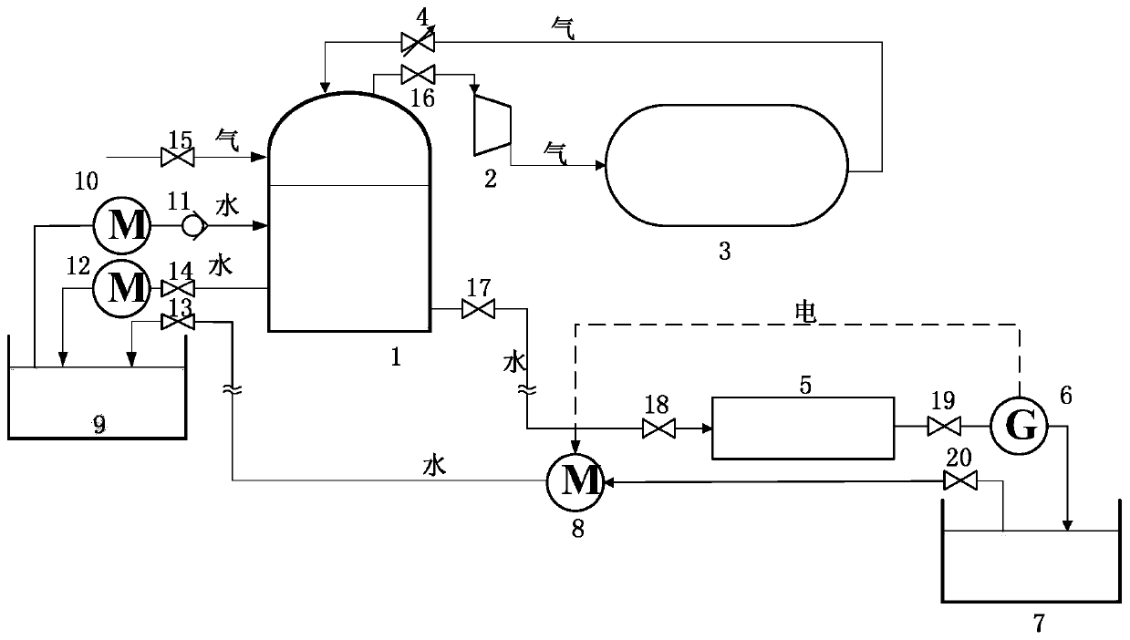
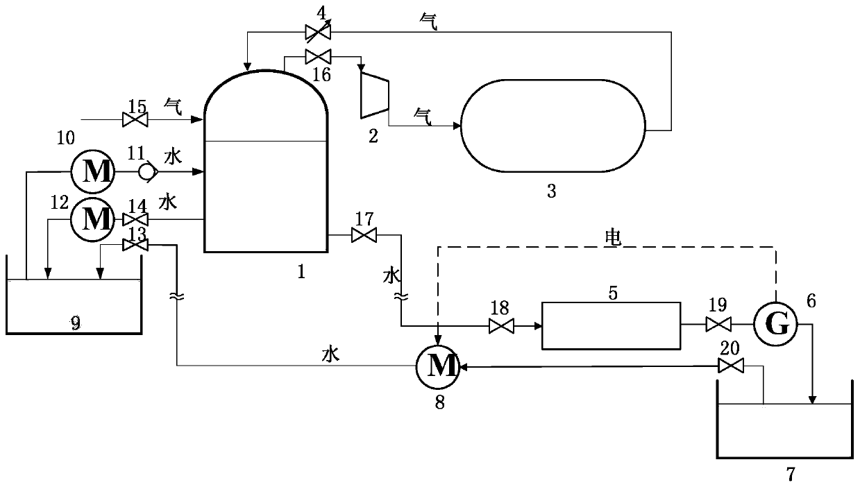
[0041] The present invention is an adjustable ultra-high flow rate and large flow water tunnel system, such as figure 1 As shown, including high-pressure water storage tank 1, booster 2, high-pressure gas storage tank 3, adjustable pressure valve 4, ultra-high-speed test water tunnel 5, water turbine 6, low-level water pool 7, low-pressure water pump 8, high-level water pool 9, high-pressure Water pump 10 and one-way check valve 11;

[0042] Wherein, adopt the parallel system of high-pressure gas storage tank 3 and high-pressure water storage tank 1, this system also includes supercharger 2 and the pressure stabilizing valve 16 in series in the middle; An adjustable pressure valve 4 is set between them to ensure that the high-pressure water storage tank 1 maintains a constant and adjustable ...


PUM


Abstract

The invention relates to a controllable ultrahigh-flow rate large-flow water tunnel system and a control method. The controllable ultrahigh-flow rate large-flow water tunnel system and the control method have the advantages of ingenious structure, reasonable design, simplicity and reliability in implementation, high water pressure, large water flow, controllability in pressure and flow, and low water flow cavitation. The system comprises a high-pressure water storage tank, a supercharger, a high-pressure gas storage tank, an adjustable pressure valve, an ultrahigh-speed test water tunnel, a water turbine and generator assembly, a low-level pool and a high-level pool; the upper part of the high-pressure water storage tank is filled with a gaseous medium; the lower part of the high-pressurewater storage tank is filled with an aqueous medium; the upper part of the high-pressure water storage tank is connected with the supercharger, the high-pressure gas storage tank and the adjustable pressure valve sequentially, and then the adjustable pressure valve is connected with the upper part of the high-pressure water storage tank, so that a gas loop can be formed; the lower part of the high-pressure water storage tank is connected with the ultrahigh-speed test water tunnel, the water turbine and generator assembly, the low-level pool and the high-level pool, and then the high-level poolis connected with the lower part of the high-pressure water storage tank, so that a water loop can be formed; a low-pressure water pump is arranged between the low-level pool and the high-level watertank; a high-pressure water pump is arranged between the high-level pool and the high-pressure water storage tank; and the high-pressure water tank is provided with an air inlet and a water outlet.

Description

technical field [0001] The invention relates to experimental fluid mechanics, in particular to a controllable ultra-high flow rate and large flow water tunnel system and a control method. Background technique [0002] High-speed water tunnels are indispensable and important equipment for the study of underwater high-speed moving bodies, and are one of the important equipment for the study of fluid mechanics. However, there are not many research institutions with high-speed water tunnels with large cross-sections at home and abroad. The equipment is shown in Table 1 below. [0003] Table 1 Some foreign water tunnel equipment [0004] [0005] [0006] At present, there are only three high-speed water tunnels in the world: 1) the ultra-high-speed water tunnel of Pennsylvania State University in the United States, with a water speed of 83.8m / s and a cross-sectional diameter of 0.038m; 2) the high-speed water tunnel of the Swiss Hydraulic Machinery Laboratory. Water tunn...

Claims


Application Information

Patent Timeline
Patent Type & Authority Patents(China)
IPC IPC(8): G01M10/00
CPCG01M10/00
Inventor 王焕然李丞宸刘明明严凯
Owner XI AN JIAOTONG UNIV
Learn More