Broadband differentially fed microstrip filter antenna

A differential feeding and microstrip filtering technology, applied in the direction of antenna, antenna grounding device, antenna grounding switch structure connection, etc., can solve the problems of increasing the overall size of the structure, increasing the RF front-end loss, reducing the antenna gain, etc. Insertion loss, easy integration, good effect of cross-polarization

Active Publication Date: 2020-03-17
HANGZHOU DIANZI UNIV
View PDF2 Cites 0 Cited by
  • Summary
  • Abstract
  • Description
  • Claims
  • Application Information

AI Technical Summary

Problems solved by technology

At present, most filter antennas use the traditional single-port feeding method. When they are integrated with differential RF front-ends, they need to use a balun structure for balanced and unbalanced conversion. The introduction of the balun structure will increase the loss of the RF front-end. Increase the overall size of the structure
In addition, the current design of the filter antenna mainly adopts the collaborative design method. In the broadband structure, multi-stage resonators need to be added, which will introduce more losses and reduce the antenna gain.
[0004] It can be seen from the above that there are few implementation methods of differentially fed filter antennas in the prior art, especially simple and compact broadband differentially fed filter antennas

Method used


Image

  • Broadband differentially fed microstrip filter antenna
  • Broadband differentially fed microstrip filter antenna
  • Broadband differentially fed microstrip filter antenna

Examples


Embodiment Construction

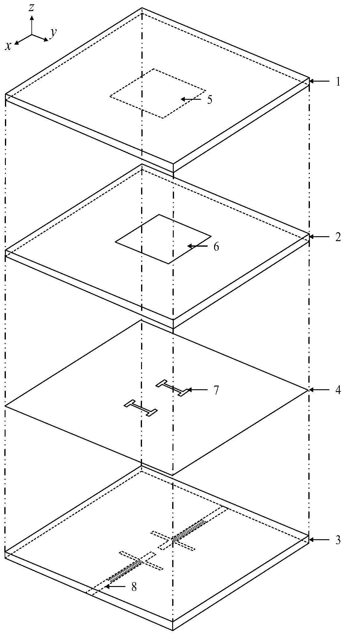
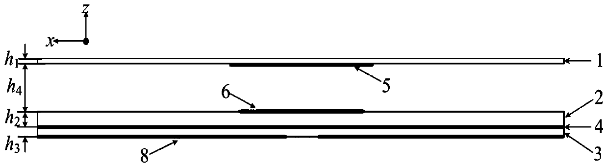
[0027] The present invention will be described in further detail below in conjunction with the accompanying drawings. combine figure 1 with figure 2 , a broadband differentially fed microstrip filter antenna, including an upper dielectric substrate 1, an intermediate dielectric substrate 2, a lower dielectric substrate 3, a ground plane 4, a square parasitic patch 5, a square radiation patch 6, a coupling slot 7, and a feeding micro Strip line 8.

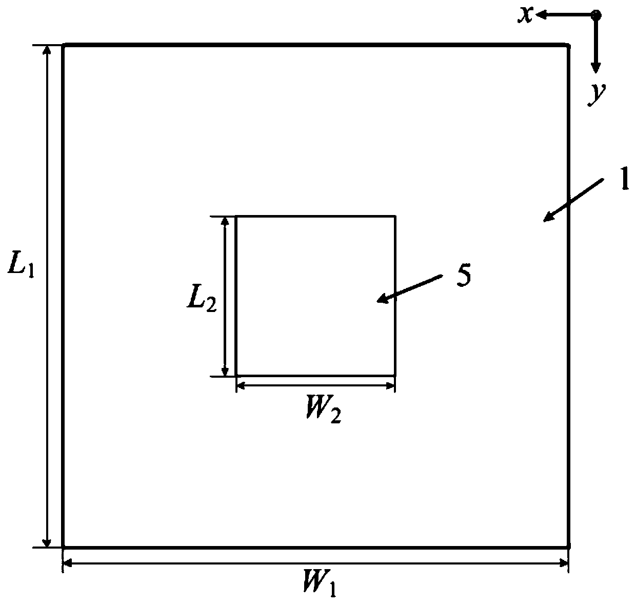
[0028] The dielectric substrate 1 is on the uppermost layer, and the dielectric substrate 2 is in the middle, separated by an air gap of a certain thickness. The dielectric substrate 3 is on the lowermost layer, separated from the dielectric substrate 2 by the ground plane 4 . The square parasitic patch 5 is located at the center of the lower surface of the dielectric substrate 1 , and the square radiating patch 6 is located at the center of the upper surface of the dielectric substrate 2 . Two H-shaped coupling slots 7 are carv...


PUM

PropertyMeasurementUnit
thicknessaaaaaaaaaa
thicknessaaaaaaaaaa
thicknessaaaaaaaaaa

Abstract

The invention relates to a broadband differential feed microstrip filtering antenna, and aims at overcoming that a traditional microstrip antenna is narrowband and incapable of gain selection. The antenna in the invention comprises three dielectric substrates, an air layer between the upper and middle dielectric substrates, a main radiation patch positioned in the upper surface of the middle dielectric substrate, a parasitic patch positioned in the lower surface of the upper dielectric substrate, the floor with a pair of slits, and a feed microstrip line positioned in the lower surface of thelower substrate and provided with a pair of branches and resonance slits; and the main radiation patch and the parasitic patched covered by the medium generate resonance, the broadband and high-gain radiation passband are provided, and a zero gain point in the edge of the passband is generated. The radiation characteristic of the antenna is further improved via a differential feed technology, andminiaturized and integrated design is easy to realize. The antenna provided by the invention is simple in structure, wider in bandwidth, high in selectivity, can be processed via PCB technology, low in processing cost and capable of large-scale production.

Description

technical field [0001] The invention relates to the field of wireless communication antennas, in particular to a microstrip filter antenna in the form of broadband differential feeding, which can be used as an antenna at the front end of a radio frequency transceiver and is widely used in wireless communication systems such as mobile communication, satellite communication, and radar. Background technique [0002] With the rapid development of wireless communication technology, the number and complexity of RF front-end system structures have increased dramatically, and multi-functional modules with miniaturization and integration characteristics have received more and more attention. The antenna and the filter are two important components of the RF front-end, and they are also the two largest components. They are usually connected by a 50Ω transmission line, which will cause a mismatch between the two components, and the overall volume of the RF front-end is large and the loss...

Claims


Application Information

Patent Timeline
Patent Type & Authority Patents(China)
IPC IPC(8): H01Q1/36H01Q1/48H01Q1/50H01Q5/50
CPCH01Q1/36H01Q1/48H01Q1/50H01Q5/50
Inventor 罗国清王华珍金华燕钱雅惠潘柏操
Owner HANGZHOU DIANZI UNIV
Why Eureka
Try Eureka