A multi-antenna energy transmission device, method and device

A technology of energy transmission and multi-antenna, applied in the direction of circuit devices, electrical components, etc., can solve problems such as low conversion efficiency, failure to work normally, and radio frequency energy voltage exceeding the saturation voltage

Active Publication Date: 2021-08-13
GUANGDONG UNIV OF TECH
View PDF8 Cites 0 Cited by
  • Summary
  • Abstract
  • Description
  • Claims
  • Application Information

AI Technical Summary

Problems solved by technology

[0005] For the rectifier used to convert radio frequency energy into direct current in the receiving device, due to the existence of nonlinear components such as capacitors and inductors in its circuit design, when the input voltage is lower than the initial voltage, the circuit stops working; and when the When the input voltage is greater than the saturation voltage, the converted electric energy tends to be saturated, resulting in a nonlinear relationship between the energy conversion efficiency and the input RF energy, which makes it impossible to fully convert the RF energy into electrical energy when it is in the nonlinear region.
[0006] For the first structure, each antenna is connected to a rectifier. When the RF energy is transferred to DC, the output voltage of a single rectifier is too low due to the initial voltage, so it cannot work normally.
In the second structure, all antennas are connected to a rectifier, which will cause the RF energy voltage input by the rectifier to exceed the saturation voltage, resulting in low conversion efficiency

Method used


Image

  • A multi-antenna energy transmission device, method and device
  • A multi-antenna energy transmission device, method and device
  • A multi-antenna energy transmission device, method and device

Examples


Embodiment Construction

[0054] The following will clearly and completely describe the technical solutions in the embodiments of the present invention in conjunction with the accompanying drawings in the embodiments of the present invention. Obviously, the described embodiments are only some of the embodiments of the present invention, not all of them. Based on the embodiments of the present invention, all other embodiments obtained by persons of ordinary skill in the art without making creative efforts belong to the protection scope of the present invention.

[0055] In order to enable those skilled in the art to better understand the solution of the present invention, the present invention will be further described in detail below in conjunction with the accompanying drawings and specific embodiments.

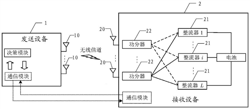
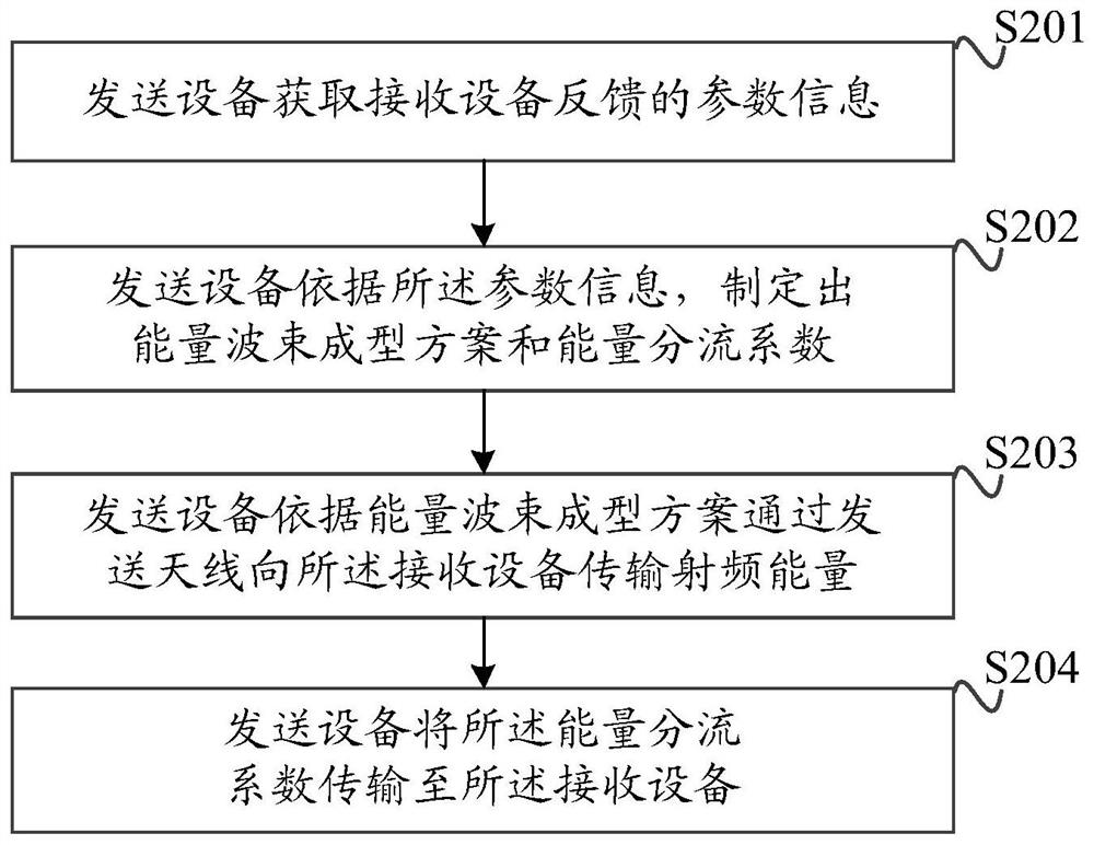
[0056] Next, a multi-antenna energy transmission device provided by an embodiment of the present invention is introduced in detail. figure 1 A schematic structural diagram of a multi-antenna energy t...


PUM


Abstract

The embodiment of the present invention discloses a multi-antenna energy transmission device, method and device, including a sending device and a receiving device, the sending device includes a plurality of sending antennas; the receiving device includes a plurality of receiving antennas, a plurality of rectifiers and a power splitter ; The sending device formulates an energy beamforming scheme and an energy split coefficient according to the parameter information, and transmits radio frequency energy to the receiving device according to the energy beamforming scheme, and transmits the energy splitting coefficient to the receiving device at the same time. Each receiving antenna in the receiving device can transmit the received RF energy to the corresponding power splitter; each power splitter is connected to the corresponding rectifier, and can adaptively split the RF energy collected by the receiving antenna according to the energy split coefficient processing, so as to ensure that the radio frequency energy transmitted to each rectifier is within an appropriate range, effectively solving the problem that the rectifier is limited by the initial voltage and saturation voltage, resulting in low energy conversion efficiency, and improving the conversion efficiency of radio frequency energy.

Description

technical field [0001] The present invention relates to the technical field of wireless transmission, in particular to a multi-antenna energy transmission device, method and device. Background technique [0002] Nowadays, electronic devices such as mobile phones, Bluetooth headsets, tablet computers and various wearable devices have been widely used, and the charging requirements for electronic devices are becoming more and more frequent. Wireless charging technology can get rid of the shackles of wired charging and has the characteristics of convenience. According to the scope of application and working principle, the current wireless charging technology can be divided into: inductive coupling, magnetic coupling resonance, electromagnetic radiation and laser beam. [0003] Electromagnetic radiation has the advantages of large transmission distance, wide range, and is convenient to transmit energy to multiple receivers at the same time. Its application prospects are very br...

Claims


Application Information

Patent Timeline
Patent Type & Authority Patents(China)
IPC IPC(8): H02J50/20H02J50/80
CPCH02J50/20H02J50/80
Inventor 马刚刚许杰
Owner GUANGDONG UNIV OF TECH
Why Eureka
Try Eureka