Supercharge Your Innovation With Domain-Expert AI Agents!

Composite type permanent magnet for synchronous permanent magnet motor rotor

A technology for permanent magnet motors and permanent magnets, which is applied to magnetic circuits characterized by magnetic materials, magnetic circuit rotating parts, magnetic circuit shape/style/structure, etc. Problems such as large dosage and large sheath stress can achieve the effects of saving material consumption, reducing the cost of permanent magnets, and reducing consumption

Pending Publication Date: 2018-11-20
NANJING CIGU TECH CORP LTD
View PDF0 Cites 1 Cited by
  • Summary
  • Abstract
  • Description
  • Claims
  • Application Information

AI Technical Summary

Problems solved by technology

[0004] 1) The amount of permanent magnet material is large, the cost is high and resources are wasted
[0005] 2) The stress of the permanent magnet sheath is very high, so expensive high-strength alloy materials must be used
[0007] In order to keep the interference connection between the permanent magnet and the sheath reliable and to offset the loosening caused by the thermal expansion gap, the stress of the sheath is very large (in some cases it can reach 700-1000MPa), so that expensive high-strength alloy materials must be used

Method used


Image

  • Composite type permanent magnet for synchronous permanent magnet motor rotor
  • Composite type permanent magnet for synchronous permanent magnet motor rotor
  • Composite type permanent magnet for synchronous permanent magnet motor rotor

Examples


Embodiment Construction

[0024] The present invention will be further described below in conjunction with the accompanying drawings.

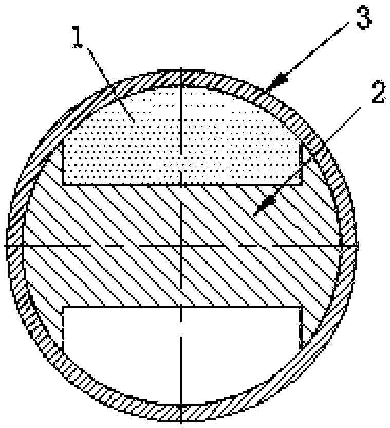
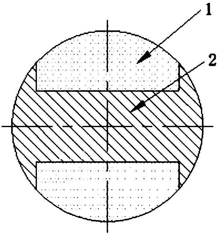
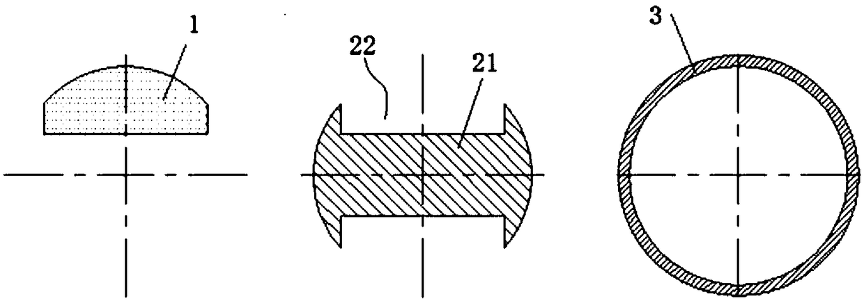
[0025] Such as Figure 1 to Figure 3 , the invention discloses a composite permanent magnet for a synchronous permanent magnet motor rotor, comprising a permanent magnet 1, a permanent magnet bracket 2 and a permanent magnet sheath 3, two permanent magnets 1 are symmetrically fixedly connected to the outer wall of the permanent magnet bracket 2, and The permanent magnet 1 and the permanent magnet bracket 2 form a cylindrical composite permanent magnet unit whose outer wall is smooth, and the permanent magnet sheath 3 is set on the composite permanent magnet unit, and the permanent magnet sheath 3 and the composite permanent magnet unit pass surplus cooperation.

[0026] The permanent magnet bracket 2 in the present invention includes a cylindrical body 21 , and two rectangular mounting grooves 22 are symmetrically provided on the outer peripheral wall of the body 21 ,...


PUM


Abstract

The invention discloses a composite type permanent magnet for a synchronous permanent magnet motor rotor, comprising permanent magnets, a permanent magnet support and a permanent magnet sheath, the two permanent magnets are symmetrically fixedly connected on the outer wall of the permanent magnet support, the permanent magnets and the permanent magnet support form a cylindrical composite permanentmagnet unit with a smooth outer wall surface, the permanent magnet sheath is sheathed on the composite permanent magnet unit, and the permanent magnet sheath and the composite permanent magnet unit are in interference fit; and the permanent magnet support is made from low-carbon steel. The composite type permanent magnet disclosed by the invention reduces consumption of permanent magnet materials, greatly reduces cost and can directly replace the original cylindrical permanent magnet part, thus a production line does not need to be changed; and high-strength alloy steel can be replaced by adopting austenitic stainless steel, thus material cost of the permanent magnet sheath is reduced.

Description

Technical field: [0001] The invention relates to a composite permanent magnet for a synchronous permanent magnet motor rotor. Background technique: [0002] Due to the high speed of the magnetic levitation motor, the volume is much smaller than that of the ordinary motor. Therefore, some medium-power magnetic levitation permanent magnet motors have adopted monolithic permanent magnets that are simple to manufacture. There are two advantages of doing this: first, the rotor has a simple structure and is easy to manufacture; second, the rotor mandrel can be made of non-magnetic materials, so as to prevent the magnetism of the rotor permanent magnet from interfering with the work of the magnetic bearing. [0003] But the disadvantages of integral permanent magnets are also obvious: [0004] 1) The amount of permanent magnet material is large, the cost is high and resources are wasted. [0005] 2) The stress of the permanent magnet sheath is very large, and expensive high-stre...

Claims


Application Information

Patent Timeline
Patent Type & Authority Applications(China)
IPC IPC(8): H02K1/27H02K1/02
CPCH02K1/02H02K1/27
Inventor 胡思宁熊伟华吴立华董继勇
Owner NANJING CIGU TECH CORP LTD
Features
  • R&D
  • Intellectual Property
  • Life Sciences
  • Materials
  • Tech Scout
  • Unparalleled Data Quality
  • Higher Quality Content
  • 60% Fewer Hallucinations
Learn More