New power electronic transformer topological structure

A technology of power electronics and topology structure, which is applied in the direction of high-efficiency power electronics conversion, adjustment of electrical variables, instruments, etc., can solve problems such as complex circuit topology, low operating efficiency, overvoltage, etc., achieve high conversion efficiency, high operating efficiency, reduce The effect of small withstand voltage

Inactive Publication Date: 2018-11-20
SHANGHAI DIANJI UNIV
View PDF1 Cites 9 Cited by
  • Summary
  • Abstract
  • Description
  • Claims
  • Application Information

AI Technical Summary

Problems solved by technology

[0003] However, the existing power electronic transformers generally have the problems of complex circuit topology, low operating efficiency and high cost. At the same time, the existing traditional AC / DC / AC power electronic transformers will appear over-current and over-voltage when they are used in high-power applications. and harmonic oscillation

Method used


Image

  • New power electronic transformer topological structure
  • New power electronic transformer topological structure
  • New power electronic transformer topological structure

Examples


Embodiment Construction

[0026] According to the attached Figure 1 ~ Figure 4 , give a preferred embodiment of the present invention, and give a detailed description, so that the functions and characteristics of the present invention can be better understood.

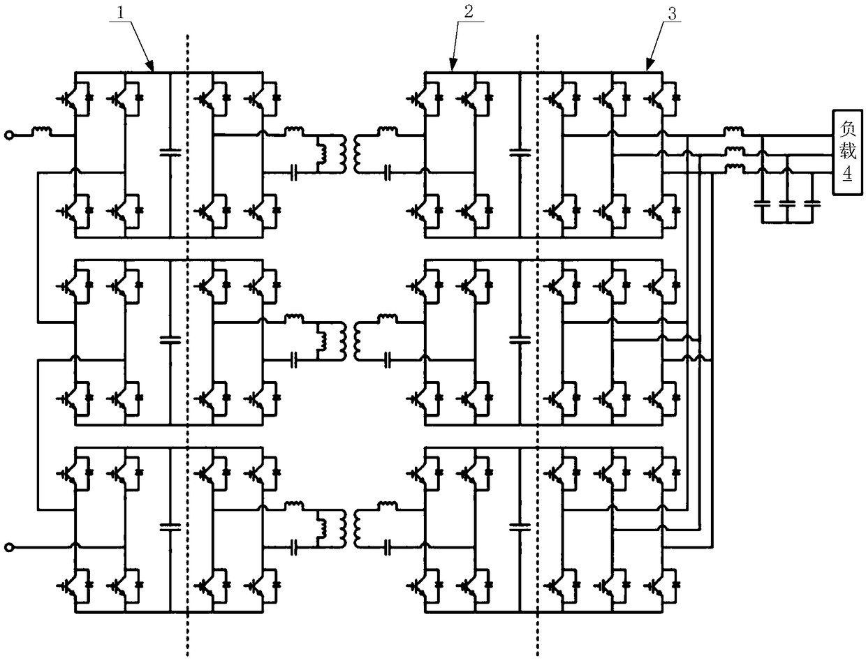
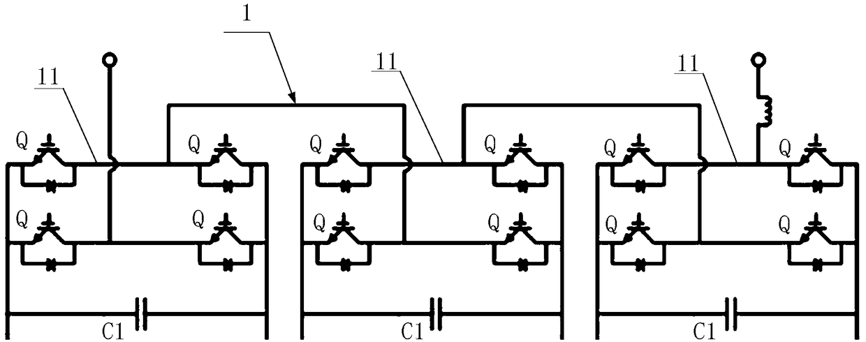
[0027] see figure 1 and figure 2 , the embodiment of the present invention provides a novel power electronic transformer topology, including an input stage circuit 1, an isolation stage circuit 2 and an output stage circuit 3 connected in sequence, and the input stage circuit 1 includes three first H-bridge circuits 11 and three DC capacitors C1, the first H-bridge circuit 11 is cascaded in sequence, and a DC capacitor C1 is connected between the two output terminals of each first H-bridge circuit 11; the first H-bridge circuit 11 is composed of four IGBTQs.

[0028] A new type of power electronic transformer topology in the embodiment of the present invention, its input stage circuit 1 includes a first H-bridge circuit 11, which can realiz...


PUM


Abstract

The invention provides a new power electronic transformer topological structure. The new power electronic transformer topological structure comprises an input stage circuit, an isolation stage circuitand an output stage circuit connected successively; wherein the input stage circuit comprises three first H-bridge circuits and three first DC capacitors, the first H-bridge circuits are cascaded insequence, and the first DC capacitor is connected between the two output ends of each first H-bridge circuit; and the first H-bridge circuit is composed of four IGBTs. The new power electronic transformer topological structure provided by the invention can quickly respond to the case of load imbalance and stabilize the system, can avoid sudden change and distortion of electrical quantities such asvoltage and current, and can avoid the damage of the device.

Description

technical field [0001] The invention relates to the field of power electronics, in particular to a novel power electronics transformer topology. Background technique [0002] The early research on power electronic transformers was limited by the development level of high-power power electronic devices and high-voltage high-power conversion technology at that time, and the various design schemes proposed could not be put into practical use. Into the late 1990s, new progress appeared in the research of power electronic transformers. Our country began to carry out research on power electronic transformers around 2002, mainly focusing on new circuit topologies, control strategies for high-efficiency operation, and loss analysis and evaluation methods. After several years of research, power electronic transformers have gradually entered the market, which has promoted the development of power transmission and distribution systems and improved the intelligence level of existing po...

Claims


Application Information

Patent Timeline
Patent Type & Authority Applications(China)
IPC IPC(8): H02M5/458H02M3/335H02M1/12
CPCH02M1/12H02M3/33576H02M5/4585Y02B70/10
Inventor 胡世勇邹海荣
Owner SHANGHAI DIANJI UNIV
Why Eureka
Try Eureka